| Command | CAPCAD_ALIGNMENT_MANAGER |
| Shortcut | EIXOS (also PROJ) |
| Ribbon | CapCad tab › Project panel › Design split button › Alignment Manager |
| Category | Manage: Project |
| Form | AlignmentManagerForm (modeless, one instance: running the command again brings the open form to the front) |
| Hosts | AutoCAD |
| Also opened by | CAPCAD_ALIGNMENT_TOOLS (opens it on the Actions tab); the Civil 3D utilities; and every alignment command that finds no alignment in the drawing offers to open it |
The alignment is the backbone of a CapCad project, and this is where you build it. A CAD polyline is only geometry. The Alignment Manager turns it into a named project alignment with segments, stations, a direction, a type and properties, saved in a .capcad file that every other CapCad command reads.
- One definition, everything hangs off it. Chainage, station labels, sign and road-marking insertion, vertical profiles, reports, GIS exports and the KM readouts all work from the alignment you define here, not from a loose polyline.
- Stations that mean something. Each segment carries its initial station, a length factor and, when needed, station equations, so km values match the field, not the drawing units.
- Built from what you already drew. Pick lines, polylines and arcs; the end you click becomes the start. Split, reorder, reread after editing, or import from LandXML and Civil 3D.
- Lanes, shoulders and markings in one click. The Carriageway tab lays the pavement, shoulders, edge lines, lane lines and the double centre line along the alignment, on the CapCad layers.
- Right of way, annotations, exports. Closed right-of-way strips, PC/PT and radius annotations, station blocks, and quick exports to capjson, KML, GPX, Esri JSON or an AutoCAD script.
- Samples to learn from. Five sample alignments load with one click, so you can try every tab before touching your own project.
What it does
The Alignment Manager creates and maintains the project alignment ("eixo"): an ordered list of segments, each one a curve taken from the drawing (line, polyline, arc), with its own station data (initial station, length factor, equations), an optional type (highway, one-way carriageway, two-way carriageway, access, edge) and a name. The alignment is saved as <name>.capcad in the project's alignments folder, and the drawing remembers which project folder and which alignment file are active.
Around that core the form offers seven tabs:
| Tab | What it is for |
|---|---|
| Manage | Project folder, active alignment file, quick whole-alignment properties (design speed, road class, road type), coordinate system, LandXML / Civil 3D import. |
| Actions | Draw the centre line, kerbs, profile and auxiliary alignments; add station blocks (chainage); PC/PT and radius annotations; municipality crossings and quick web map. |
| Carriageway and lanes | Build the pavement, shoulders, median and road markings along the alignment. |
| Properties | Station format, type and name of the selected segment; free-form properties on the alignment or a segment. |
| Right of way | Closed right-of-way strips between two stations, or one strip every n metres. |
| Utils | Quick exports, tangency check, plot every alignment of the project, duplicate / export the alignment, clear the drawing's project data. |
| Options | List Civil 3D alignments, ask name and type, LandXML sample. |
The bottom half of the form is the same on every tab: the segment list, the sample buttons and the action row (add, split, draw, zoom).
Workflow
- Run
CAPCAD_ALIGNMENT_MANAGER(or typeEIXOS). If the drawing has no project yet but you used one recently, the form offers to reuse it (Yes, No or Only folder). - On the Manage tab, set the Project folder (type or paste a path, use … (22), or Use dwg folder (21)). The folder must exist; the box turns pink while it does not.
- Type a name in the Active box and click Create new (26). The name gets the
.capcadextension; the file is written when the first segment is added. To reopen an existing alignment, pick it from the list and click Make Current. - Click Add 1 Segment (8) and pick a curve in the drawing, near the end you want to start from. Repeat, or use Add many Segments (9). The list fills with lengths and stations.
- Fix the stations: double-click a row to edit its factor, initial station and equations; use Split Segment (10), ↑ ↓ (3, 4) and Del (5) to shape the list.
- Click Draw alignment (12) to put the alignment on its own layer, then use the Actions tab (Create, 53) for chainage and annotations, the Carriageway and lanes tab (Create, 73) for the pavement and markings, and the Right of way tab (Generate, 92) for right-of-way strips.
- Close with Exit (14). Your options are remembered; the alignment file is already saved: every change on the form writes it at once.
The form
Numbers are the same in every screenshot of this page. The area below the tabs (segment list, samples, action row) is shared by all tabs and keeps numbers 1 to 19; each tab continues from 20. Controls without a number (the two combo boxes on Manage, the segment list, the double-click radios, a few check boxes and combos) have no internal name and are described by their caption.
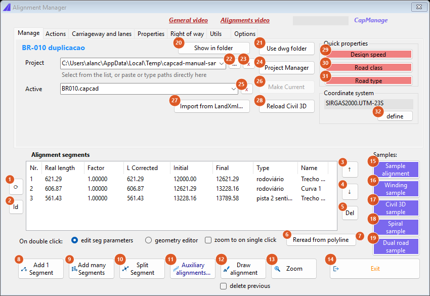
Manage tab with a sample project loaded: three segments with their real length, factor, corrected length, initial and final stations, type and name.
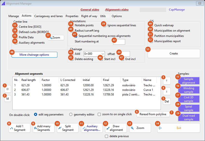
Actions tab: centre line group, annotations, chainage, GIS and the Create button.
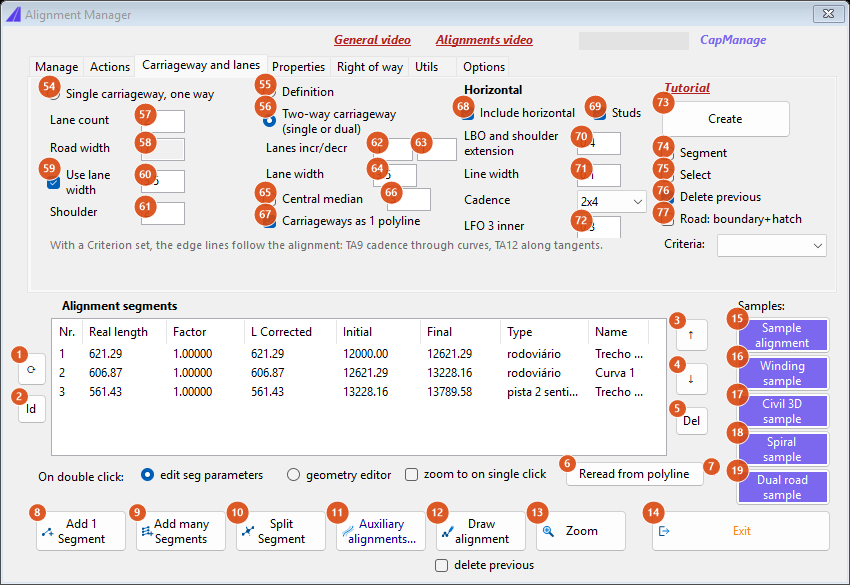
Carriageway and lanes tab, default values: two-way carriageway, 1 + 1 lanes of 3.5, shoulder 2, markings with studs, cadence 2x4.
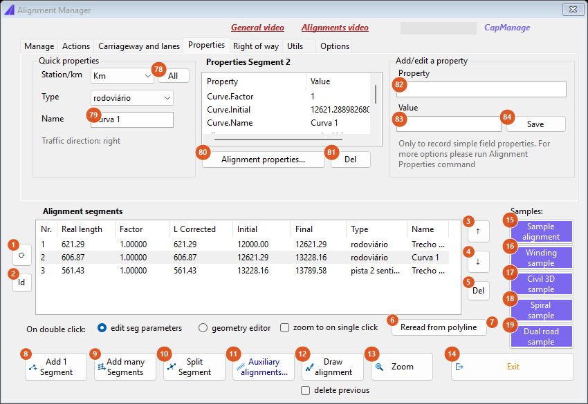
Properties tab with segment 2 selected: quick properties on the left, the segment's property bag in the middle, the add/edit box on the right.
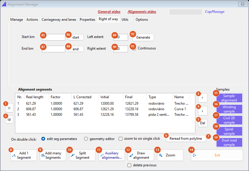
Right of way tab: one strip between two stations.
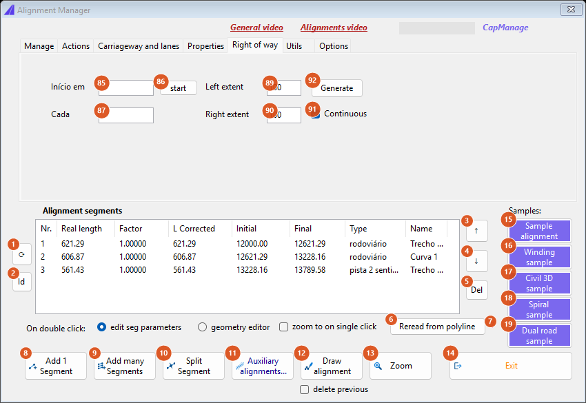
The same tab with Continuous (91) on: the two station boxes become "start at" and "every", and the end button (88) hides.
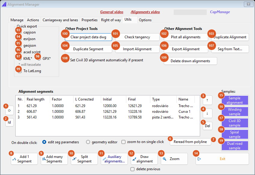
Utils tab: quick export formats, project tools and alignment tools.
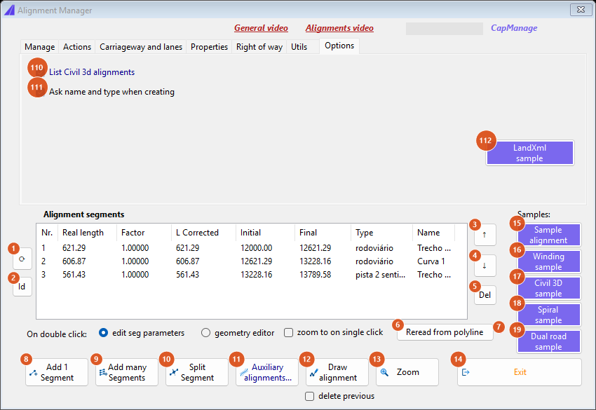
Options tab.
Segment list and action row (shared by every tab)
| # | Control | What it does |
|---|---|---|
| — | Alignment segments list | One row per segment: Nr. (1-based), Real length (drawn length), Factor (length factor, 5 decimals), L Corrected (factor × length), Initial and Final station, Type, Name. A closed segment shows - in the station columns and Area as type; a segment with station equations shows <equations> instead of L Corrected and Final. A single click selects the segment: the Properties tab switches to it and, with zoom to on single click ticked, the drawing zooms to it. A double click does what the On double click choice says. |
| — | On double click: edit seg parameters (default) | Double-clicking a row opens the Segment edit dialog for that segment: length factor, initial and final station (the final can adjust the factor or the initial extent), real versus corrected length, the station equations (read-only list), plus Delete segment, Invert direction, Reset values and Single Curve Editor… (which opens the Curve Tangency assistant after the dialog closes). The form hides while the dialog is open and reloads the list afterwards. |
| — | On double click: geometry editor | Double-clicking asks Alignment N is not drawn, required for editing. Draw now?; Yes draws the segment and reminds you to reload the edited polyline afterwards (with Reread from polyline). |
| — | zoom to on single click | Zoom the drawing to the segment you click in the list. Remembered between sessions. |
| 1 | ⟳ | Reload the alignment file from disk and refill the list and the properties. |
| 2 | Id | Identify by point: the form hides, you pick a point in the drawing, and the segment whose perpendicular foot is nearest (within 5000 drawing units) is selected in the list. No zoom. |
| 3, 4 | ↑ ↓ | Move the selected segment one position up or down (the two rows swap) and save. |
| 5 | Del | Delete the selected segment after Confirm deletion of alignment segment nr N?. The last remaining segment cannot be deleted. |
| 6 | Reread from polyline | Re-read the geometry of every segment from the entity it was drawn as (the drawn entity's handle is stored on the segment by Draw alignment). Properties and stations are kept; only the vertices change. Fails with Could not reread the alignment that had been drawn… when a drawn entity is gone. |
| 7 | ? (pink) | Reminder: editing a drawn alignment does not update its definition; remove and add it again, or use Reread from polyline. |
| 8 | Add 1 Segment | The form hides and you pick one line, polyline or arc. The end nearest to where you clicked becomes the start of the segment. Linetype, linetype scale, lineweight, constant width and layer are reset on the copy. A polyline with elevation ≠ 0 raises a warning with Cancel / Continue anyway (the elevation is not carried into the alignment). The segment is appended and the file saved. If no project or alignment is set yet, the command says so and stops. |
| 9 | Add many Segments | First a note: multiple segments are not checked for tangential consistency and keep the vertex order of the selected geometry (Continue?, can be silenced for the session). Then select any number of lines, polylines, arcs or splines; they are appended in selection order, without reversing. |
| 10 | Split Segment | Pick a point; the open segment whose perpendicular foot is nearest is cut there. Both halves inherit the segment's properties; the first keeps the initial station, the second starts at the station of the split point (equations honoured). The original is removed and the two halves are appended at the end of the list (see figure). |
| 11 | Auxiliary alignments… | Opens CAPCAD_ALIGNMENT_AUXILIARY. |
| 12 | Draw alignment | Draws the selected segment, or the whole alignment when nothing is selected: one polyline per segment on the layer the layer catalogue gives to the alignment (CAPCAD_EIXO-[type-]name in the default style), coloured by type (one-way = 1, two-way = 5, access = 93, edge = 4, highway = 2, untyped = 6), linetype SETA_CONT_1 at scale 20, with a constant width. Every entity is tagged with DrawnAlignment xdata and its handle is stored on the segment (for Reread from polyline); the file is saved with the refreshed layers and handles. |
| — | delete previous | Tick before Draw alignment: every entity carrying the DrawnAlignment tag is erased first. The box unticks itself after the draw. |
| 13 | Zoom | Zoom to the selected segment, or to the whole alignment. |
| 14 | Exit | Close the form. |
| 15 | Sample alignment | After Proceed?, downloads the sample BR010.capcad from the CapCloud service into Samples\SampleProject, makes it the project and alignment, and shows the CapLearn welcome message. |
| 16 | Winding sample | Same with the winding sample peru.capcad, without the welcome message. |
| 17 | Civil 3D sample | After Proceed?, downloads the Civil 3D sample drawing from the CapServer and opens it in a new document. |
| 18 | Spiral sample | Downloads the spiral sample alignment into the Exports folder and makes it current (no confirmation). |
| 19 | Dual road sample | Downloads the alignment-types sample (a dual carriageway with typed segments) and makes it current (no confirmation). |
| — | General video, Alignments video | Open the two tutorial videos on YouTube. |
The status line under the videos shows Loading sample… while a sample downloads. Every sample click is logged as a CapLearn usage entry.
Tab 1: Manage
| # | Control | What it does |
|---|---|---|
| — | project name (blue) | The project's name: the ProjectName item of the project configuration, or the folder name. |
| — | Project combo | The project folder. The list holds the current folder and the last one used. Type or paste a path: as soon as it exists it becomes the project folder (the box is white and the alignment list refreshes); while it does not exist the box is pink and nothing changes. |
| 22 | … | Browse for the project folder. |
| 23 | x (red, project) | Forget the project folder and the active alignment in this drawing (the files stay on disk). |
| 20 | Show in folder | Opens Windows Explorer on the alignments folder with the active .capcad selected. Project folder not set. when there is none. |
| 21 | Use dwg folder | Use the folder of the saved drawing as project folder. Refused when the drawing is not saved; Already same folder when it already is; if an alignment is set, asks There is already an alignment set - it will be lost if the folder is changed. Continue?. |
| 24 | Project Manager | Opens the Project Manager dialog; the form refreshes when it closes. |
| — | Active combo | The alignment file. Lists every *.capcad in the alignments folder and, with List Civil 3d alignments (110) on, the drawing's Civil 3D alignments as <name>.capcad. Pink while the text is not in the list. |
| 25 | x (red, alignment) | Clear the active alignment: the drawing forgets the file name and the list empties. |
| 26 | Set active / Create new / Make Current | With a name that is in the list the caption reads Make Current: the file is loaded and recorded as the last-used project and alignment. With a new name it reads Create new: the name gets .capcad and the alignment starts empty; the message New alignment has been defined. Physical .capcad file will be created as the segments are fed in. appears (it has a "do not show again" option) and buttons 8 and 9 turn blue. Disabled when the box is empty or the name is already active. |
| 27 | Import from LandXml… | Pick an .xml file. The alignments in it become the project alignment, named after the LandXML alignment (or the current file name, or alignment), the initial station is the LandXML staStart, the current alignment's own properties are carried over, and the file is saved in the alignments folder (Saved to |
| 28 | Reload Civil 3D | Needs Civil 3D. Re-reads geometry and parameters from the Civil 3D alignment with the same name as the file (BR010.capcad → BR010), keeping the CapCad-side properties, saves, and reports Civil 3D alignment was reloaded. |
| 29 | Design speed (red) | Sets the design speed for the whole alignment: a prompt with a list (40 to 120 km/h, or type a value). Stored as the VelocidadeDiretriz property and confirmed with Recorded. If the speed was already set per station through Alignment properties, the button refuses with Speed already set in alignment properties. Zero or text is Invalid data. |
| 30 | Road class (red) | Sets rodovia.classe for the whole alignment: Classe 0, IA, IB, II, III, IV or V (used for sign sizes, per the norm of the active country profile). Only a value from the list is accepted. |
| 31 | Road type (red) | Sets TipoVia. The stored values are Portuguese, because they are written into the project file verbatim: Rural-Estrada (rural road), Rural-Rodovia (rural highway), Urbana (urban), Urbana (Trânsito Rápido) (urban expressway) and Área protegida (protected area). Used for sign sizes. |
| — | Coordinate system | The project's coordinate system, resolved from the alignment file, the drawing, Civil 3D or the country default. |
| 32 | define | Opens the coordinate-system picker (modeless); the label refreshes when it closes. |
Tab 2: Actions
Tick what you want and click Create (53). The actions run in this order: centre line, profile, quick web map, chainage, kerbs, auxiliary alignments, radius annotations, PC/PT annotations, municipalities. Nothing runs without an alignment.
| # | Control | What it does |
|---|---|---|
| 33 | Centre line [EIXO] | Draw the alignment, exactly as Draw alignment (12). |
| 34 | Defined curbs [BORDO] | Draw the kerb curves stored on the alignment (left, right and auxiliary kerbs), each on its own layer. If the alignment carries none: None of the 3 curb alignment properties found: left, right and auxiliary curbs. |
| 35 | Profile Data | Draw the vertical profile stored on the alignment. None: Profile data not found. |
| 36 | Auxiliary alignments | Draw the auxiliary alignments stored on the alignment, on the EIXOS_AUX layer at linetype scale 10. |
| 37 | Zoom | Same as 13. |
| 38 | Notable points | A leader at every vertex of every segment, labelled PC= or PT= with the station (12+046). The command line reports N PC/PT annotations. |
| 39 | Ignore sequential lines | With 38: a run of consecutive PT points (straight pieces following each other) is labelled once instead of at every vertex. |
| 40 | Radius/curve#/ang | A multi-line label at the midpoint of every segment piece: L= length and, for arcs, R= radius, NR= curve number and Ang= deflection. Reported as N segment annotations. |
| 41 | Sequential numbering across alignments | With 40: curve numbers run on from one segment to the next instead of restarting. |
| 42 | Start numbering at | The number the first curve gets (default 1). |
| 43 | Add (chainage) | Insert STATION blocks along every open segment whose length factor is not zero and whose type is highway, two-way carriageway or untyped: one every 20 station units, with a formatted label every 100. Each segment uses its own Station/km format (Properties tab): Km labels as 12+100 using the format combo; de 20 labels with the estaca number (station ÷ 20). Blocks go on the CAPCAD_STATION layer. |
| — | format combo (0+000) |
The major-label pattern: 0+000, 0,000 or 0.000. Only 0+000 is understood by the formatter; the other two produce a plain number. |
| 44 | offset | Perpendicular offset of every block from the alignment; positive is to the left of the walking direction. |
| 45 | Delete existing | Erase every STATION block reference in model space before inserting. Remembered between sessions. |
| 46, 47 | Start incl, End incl | Also mark the first and the last vertex of each segment. |
| 48 | More chainage options | Opens the Alignment Tools form (CAPCAD_ALIGNMENT_CHAINAGE) alongside this one. |
| 49 | Quick webmap | Runs CAPCAD_GEO_LINK_WEBMAP with the form hidden: the alignment is reprojected to WGS84 and opened as a Leaflet web map in the browser. |
| 50 | Municipalities on alignment | Needs a coordinate system (Coordinate system not defined otherwise). Fetches the municipality polygons the alignment crosses and draws them. |
| 51 | Partition municipalities | Also cuts the alignment at every municipality boundary, each stretch on its own GIS_NM_MUNICIP-<name> layer. |
| 52 | Municipalities report | Shows the crossing report (Relatório cruzamento de municípios) in a text window. |
| 53 | Create | Run the ticked actions. |
Tab 3: Carriageway and lanes
Everything on this tab feeds Create (73). Typing in Lane count or Road width selects Single carriageway, one way; typing in Lanes incr/decr selects Two-way carriageway.
| # | Control | What it does |
|---|---|---|
| 54 | Single carriageway, one way | One pavement of Road width (58) split into Lane count (57) lanes, a shoulder each side, two edge lines and the lane lines. |
| 55 | Definition | Each segment picks its own branch from its type: pista 1 sentido → one-way, pista 2 sentidos or untyped → two-way; other types are skipped. |
| 56 | Two-way carriageway (single or dual) (default) | Lanes incr (62) lanes on one side and Lanes decr (63) on the other, each of Lane width (64), separated by the double centre line (LFO-3), with shoulders and edge lines. With Central median (65) and a width above zero it becomes a dual carriageway: two one-way pavements either side of the median plus the median itself on the CANTEIRO layer at that width. |
| 57 | Lane count | One-way: number of lanes; n lanes give n − 1 lane lines. |
| 58 | Road width | One-way: total pavement width. Greyed while Use lane width (59) is on, when it equals 60 × 57. |
| 59 | Use lane width (default on) | Compute Road width from Lane width (60) × Lane count (57). |
| 60 | lane width (one-way) | The lane width used by 59. |
| 61 | Shoulder | Shoulder width, both modes, both sides. |
| 62, 63 | Lanes incr/decr | Two-way: lanes on the increasing side and on the decreasing side (the increasing side is the right of the walking direction). 0 on either side is Invalid lane values. |
| 64 | Lane width | Two-way: width of every lane. The outer lane of each side is widened by LBO and shoulder extension (70) and the inner lane by half of LFO 3 inner (72), so 1 + 1 lanes of 3.5 make a pavement of 8.1 (see figure). |
| 65, 66 | Central median, width | Two-way only: dual carriageway with a median of this width (see 56). |
| 67 | Carriageways as 1 polyline (default on) | Draw the pavement as one polyline instead of one per side. |
| 68 | Include horizontal (default on) | Draw the road markings. Off: no lane lines and no edge lines; only pavement and shoulders. |
| 69 | Studs (default on) | Put the markings on the stud layers: lane lines on SINA_HOR_BR_<cadence>TA_LMS2, edge lines on SINA_HOR_BR_TA<n>E_LBO / …TA<n>D_LBO, centre line studs on SINA_HOR_AM_TA<n>_LFO3, where n is the sum of the cadence numbers (2x4 → 6). Off: SINA_HOR_BR_<cadence>_LMS2 and SINA_HOR_BR_LBO. |
| — | Cadence combo | 1x2, 1x3, 2x4 (default), 2x6, 3x6, 3x9, 4x12: the stud cadence baked into the layer names above. |
| 70 | LBO and shoulder extension | Two-way: extra width added to the outer lane of each side (default 0.4). |
| 71 | Line width | Polyline width of every marking line (default 0.1). A value above 0.3 is refused as Invalid data and nothing is drawn. |
| 72 | LFO 3 inner | Two-way: gap between the two lines of the double centre line (default 0.3; blank or 0 falls back to 0.3). |
| — | Criteria combo | Empty (default) or the criterion offered by the active country profile. One-way: the edge lines follow the alignment's curves and tangents, on SINA_HOR_BR_TA9E/D_LBO through curves and SINA_HOR_BR_TA12E/D_LBO along tangents, 0.4 inside the pavement edge (the grey note under the fields). Two-way: the alignment is first partitioned by its design-speed bands; with none, No design-speed bands found on the alignment - the lanes are built unpartitioned. |
| 73 | Create | Build and draw. Warnings (offset failures, missing values) go to the command line, followed by N carriageway entities drawn. In two-way mode on the project alignment, the lane definition (LarguraVia) is stamped on every segment and the file saved. |
| 74 | Segment | After Create, pick two points; only the stretch between them, on the segment that contains both, is built. Points that do not project: Invalid input data. |
| 75 | Select | Build on curves you select in the drawing (lines, polylines, arcs) instead of the project alignment. |
| 76 | Delete previous (default on) | Before drawing, erase every entity on the pavement, shoulder and edge layers, and on any layer whose name contains _HOR_, ROAD_MARK or canteiro. |
| 77 | Road: boundary+hatch | Draw the pavement as a closed boundary with a hatch instead of a wide polyline. |
| — | Tutorial | Opens the carriageway tutorial video. |
Tab 4: Properties
The middle list shows the property bag of the main alignment when nothing is selected, or of the selected segment (the header reads Properties Segment N). Values that are objects (station tables, curves) show as [Object].
| # | Control | What it does |
|---|---|---|
| — | Station/km combo | Station format of the selected segment: Km, de 20 (Brazilian 20 m stakes) or Atributo. Stored on the segment (Estaca20) and used by the chainage. |
| 78 | All | Apply the chosen format to every segment (Ok). |
| — | Type combo | Alignment type of the selected segment: empty, pista 1 sentido, pista 2 sentidos, rodoviário, acesso or bordo. Drives the layer colour, the chainage filter and the Definition mode of the carriageway tab. |
| 79 | Name + Enter | Name of the selected segment (shown in the list). |
| — | Traffic direction | Read-only: the driving side of the active country profile. |
| — | property list | Click a row to copy it to 82 and 83. Rows whose name contains capcad or acad., or whose value is [Object], are system properties and cannot be edited or saved from here. |
| 80 | Alignment properties… | Opens CAPCAD_ALIGNMENT_PROPERTIES (station-indexed properties) with this form hidden. |
| 81 | Del | Delete the selected property after Delete |
| 82, 83 | Property, Value | A simple field property. |
| 84 | Save | Store the property on the main alignment or the selected segment and save the file. Values are stored as a one-row station table (0,<value>). |
Tab 5: Right of way
Works on the selected segment; without one: Select an alignment segment to proceed.
| # | Control | What it does |
|---|---|---|
| 85 | Start km | Start station of the strip. |
| 86 | start | Fill 85 with the selected segment's initial station. |
| 87 | End km | End station of the strip. |
| 88 | end | Fill 87 with the selected segment's final station. Hidden in Continuous mode. |
| 89 | Left extent | Reach to the left of the walking direction (default 100). |
| 90 | Right extent | Reach to the right (default 100). |
| 91 | Continuous | One strip after another: box 85 becomes the start station ("Início em") and box 87 the step ("Cada"); strips are generated from the start to the end of the segment. |
| 92 | Generate | Build the closed strip (the two offsets between the stations, closed by the cross lines at each end) and draw it as a closed polyline on layer FaixaDeDomínio. Invalid input data. when the stations fall outside the segment, coincide, or an offset collapses on a tight arc. |
Tab 6: Utils
| # | Control | What it does |
|---|---|---|
| 93 to 98 | capjson, esrijson, geojson, acad script, KML*, GPX* | Selecting a format renders the whole alignment in that format and shows it in a text window (copy from there). KML and GPX tesselate the curves and use the alignment's coordinate system, or the project's. geojson is Under development. |
| 99 | To LatLong | KML: convert the coordinates to latitude/longitude. Off, the coordinates are written as they are. |
| 100 | Clear project data dwg | After Projet configuration will be removed locally only in THIS dwg. Proceed?, removes the whole capcad dictionary from the drawing (project folder, alignment name and every other per-drawing setting) and clears the loaded alignment. Files on disk are untouched. |
| 101 | Check tangency | A text window with one line per segment, Eixo / Is tangent?, and the advice to use the Polyline Editor to check each vertex. |
| 102 | Plot all alignments | Needs a project (Project folder not set.). After Layer name will be alignment name., draws every .capcad of the alignments folder, each on its own EIXO_PREFIX_<file name> layer. |
| 103 | Duplicate Alignment | Asks for a new name; the alignment is saved under it and becomes the current one. File already exists when the name is taken. |
| 104 | Duplicate Segment | Under development. |
| 105 | Import Alignment | Under development. |
| 106 | Export Alignment | Writes <name>.capcad into the Exports folder and reports Saved to |
| 107 | Seg from Text… | Under development. |
| 108 | Set Civil 3D alignment automatically if present | Saved with the form; not used by this version. |
| 109 | Delete drawn alignments | Erase every entity tagged DrawnAlignment (what Draw alignment and Plot all alignments created). |
Tab 7: Options
| # | Control | What it does |
|---|---|---|
| 110 | List Civil 3d alignments (default on) | Add the drawing's Civil 3D alignments to the Active list. Remembered. |
| 111 | Ask name and type when creating (default on) | Remembered preference; not used by this version. |
| 112 | LandXml sample | Downloads the LandXML sample from the CapServer and imports it exactly as Import from LandXml… (27). |
How the options combine
The figures below were produced by running the same engines the form calls (chainage, annotations, carriageway, right of way, split) on a sample alignment of three segments: a 40 m tangent, a 56.05 m curve and a 41.23 m tangent, starting at station 12 000.
The alignment as the manager sees it
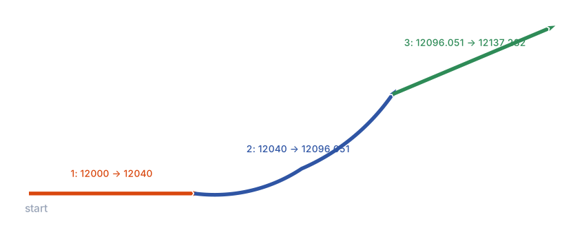
Three segments, each with its initial and final station. The arrows show the walking direction, set by the end you clicked when adding the segment.
Split Segment
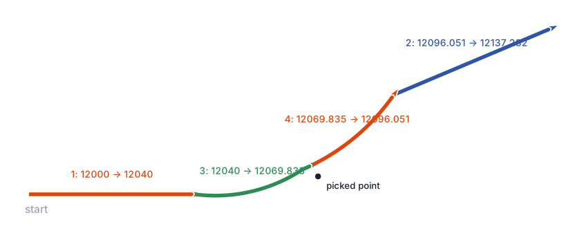
Segment 2 split at the picked point. The two halves inherit its properties and stations (12 040 to 12 069.8 and 12 069.8 to 12 096.1) and are appended at the end of the list, so the old segment 3 becomes segment 2.
Chainage
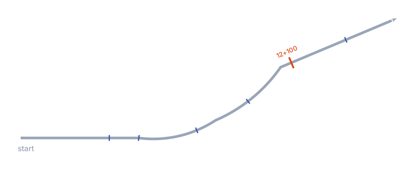
Add chainage on a single-segment alignment starting at 11 990: a mark every 20 station units, and a formatted label (12+100) every 100, in the 0+000 format.
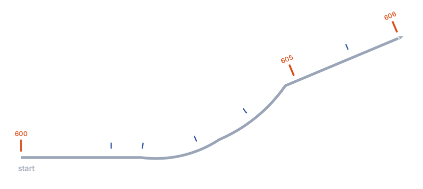
The same alignment with the segment's format set to "de 20", offset 4 and Start incl / End incl: the labels are estaca numbers (station ÷ 20: 600, 605, 606), the marks sit 4 units to the left, and both ends are marked.
Annotations
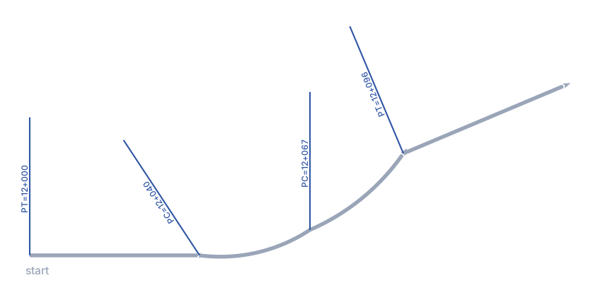
Notable points: a leader at every vertex with PC= / PT= and the station.
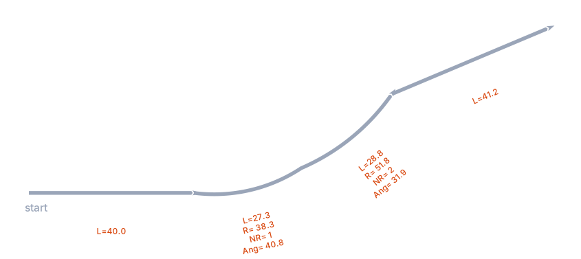
Radius/curve#/ang with sequential numbering: every piece gets its length; the two arcs also get radius, curve number (1, 2) and deflection angle.
Carriageway and lanes
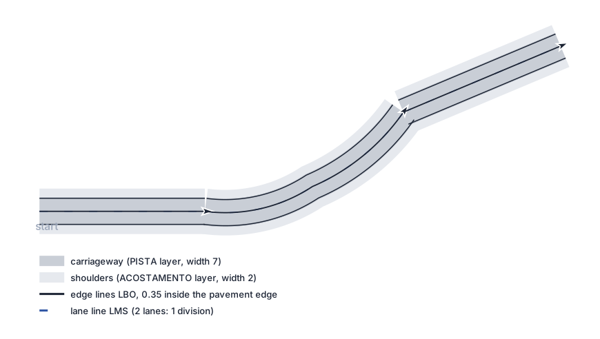
Single carriageway, one way: lane count 2, road width 7, shoulder 2. The pavement is a 7-wide polyline on the PISTA layer, the shoulders 2-wide polylines on the ACOSTAMENTO layer, the edge lines sit 0.35 inside the pavement edge and one lane line divides the two lanes.
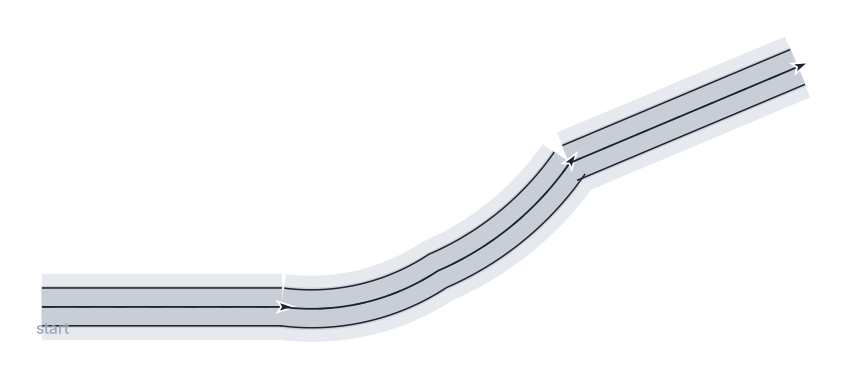
The same with Road: boundary+hatch: the pavement is a closed boundary to be hatched instead of a wide polyline.
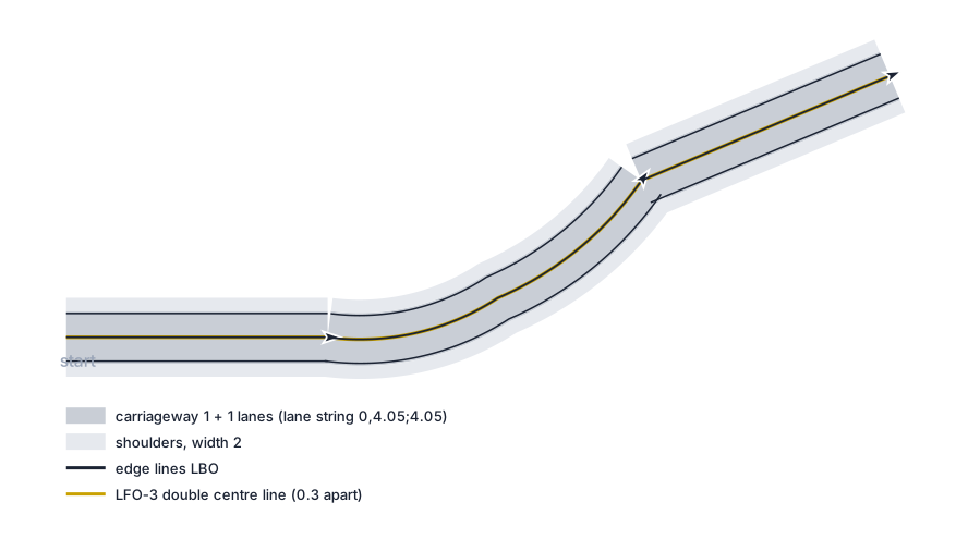
Two-way carriageway, 1 + 1 lanes of 3.5, shoulder 2, LFO 3 inner 0.3, LBO extension 0.4. The lane string built is 0,4.05;4.05: each lane is 3.5 + 0.15 (half the centre gap) + 0.4 (LBO extension), so the pavement is 8.1 wide, with the double centre line and the edge lines.
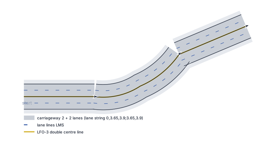
Two-way, 2 + 2 lanes: lane string 0,3.65,3.9;3.65,3.9; the lane lines appear between the lanes of each side.
Right of way
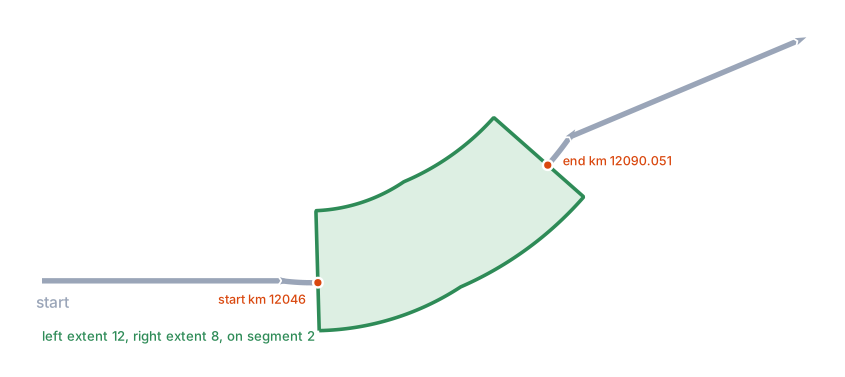
Generate on segment 2 between stations 12 046 and 12 090.05 with left extent 12 and right extent 8: one closed strip, wider on the left of the walking direction.
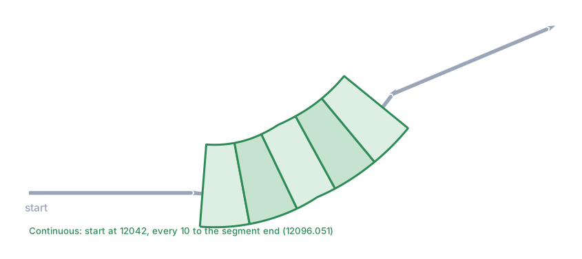
Continuous with start at 12 042 and every 10: one closed strip per step up to the end of the segment (12 096.05); a strip that would fall outside the segment is skipped.
Remembered between sessions
- zoom to on single click, List Civil 3d alignments (110), Ask name and type when creating (111) and Delete existing (45) are user preferences, saved when the form closes.
- The last project folder and alignment file are recorded each time an existing alignment is made current; they feed the last used offer when the form opens on a drawing without a project, and the second entry of the Project list.
- The project folder and the active alignment file are stored in the drawing itself (the
capcaddictionary), so they come back with the drawing. - The "do not show again" choice of the New alignment has been defined message is reset from User Preferences.
Notes
- The form is modeless and single-instance:
CAPCAD_ALIGNMENT_MANAGERopens it on Manage,CAPCAD_ALIGNMENT_TOOLSon Actions; a second run only brings it to the front and switches the tab. - Every change (add, split, reorder, delete, properties, quick properties) writes the
.capcadfile immediately; there is no separate save. - Add many Segments keeps the vertex order of each curve; Add 1 Segment reverses the curve so that the end nearest to your pick is the start. Use the Invert direction button of the Segment edit dialog to fix a segment added the wrong way round.
- The chainage of Create uses fixed intervals of 20 and 100; other intervals and station formats are on the Alignment Tools form (48).
- In Continuous mode the two right-of-way labels read "Início em" and "Cada" in every language; the values are the start station and the step.
- Set Civil 3D alignment automatically if present (108) and Ask name and type when creating (111) are saved with the form; not used by this version.
- The Traffic direction line on the Properties tab follows the active country profile; it is not editable here.