| Command | CAPCAD_MARKING_CROSSING |
| Shortcut | FX (TRA also works on AutoCAD and ZWCAD) |
| Ribbon | CapCad tab › Traffic Control panel › Transverse split button › Crossings (in the United Kingdom ribbon the same button sits under the Pedestrian Cross split button) |
| Category | Horizontal: specials |
| Form | TravessiasForm (modeless: the drawing stays live while it is open) |
| Hosts | AutoCAD. Not available in this version on ARES Commander (running it shows a notice saying so), BricsCAD, GstarCAD and ZWCAD |
| Also opened by | CAPCAD_MARKING_HUB (docks this form in the horizontal hub); the Cycle track form opens it pre-set (railway "Crossing" button: stop lines only, two-way, channelisation on both sides) |
One reference line, the whole crossing. Pick the road width once and the form builds the stripes, the stop lines, the approach lane lines, the double yellow line and the PARE legend together, then redraws them every time you change a value.
- Live preview. Every value change erases the previous result and draws it again. Accept when it looks right, Reset if it does not.
- Three ways to get the reference line. Two points on the kerbs, two kerb curves and a point, or an alignment and a point.
- Everything anchored. Choose which feature sits on the line you picked (stripe edge, centre, stop line, an offset from the stop line) and move the line between anchors without moving the marking.
- Brazilian and European variants. Zebra, black contrast, raised crossing with give-way teeth (lombofaixa), cycle crossing type 1 and 2, dashed stop line, skewed crossings.
- Presets. Six built-in configurations, typical norm values in one click, and your own saved presets.
- Grouped for later. Everything drawn in one pass carries a group id and a type tag, so
CAPCAD_SELECT_GROUPcan re-select the whole crossing later.
What it does
The command draws a pedestrian or cycle crossing across a reference line that spans the road from kerb to kerb. From that one line it derives:
- the body of the crossing: zebra stripes (with optional black contrast quads between them), a solid painted band, or the red cycle crossing;
- give-way teeth on one or both sides of the body (raised crossing, "lombofaixa");
- the stop lines before the crossing on the entry side, and on the exit side for two-way roads, solid or dashed;
- the approach channelisation: lane lines (LMS) on the approach, the double yellow line (LFO-3) between the two directions, and a PARE or DÊ A PREFERÊNCIA legend in each lane.
The first point of the reference line is one kerb, the second the other kerb. Traffic on the entry side approaches the crossing on the right-hand half of the line (looking from the first point towards the second, the entry side is on the right of the line); the exit side is the opposite one. Flip side (28) swaps them.
The result is a live preview: each change on the form (with Dynamic on) erases the previous preview and draws a new one. Accept (29) keeps it as ordinary entities; closing the form also keeps the last preview and removes only the magenta reference line.
Workflow
- Run
CAPCAD_MARKING_CROSSING(orFX). The form opens beside the drawing. - Pick a preset from the gallery at the top of the Main tab or from the Presets box (1), or set the body, stop lines and approaches by hand.
- Choose how to pick the reference line (2, 3 or 4) and click Select (6). Pick from one kerb to the other. The magenta reference line is drawn and the preview appears.
- Refine: stripe sizes (51 to 58), stop line width and distance (72, 74), lanes and approach length (77 to 85), skew angle (39), anchor (11 to 27).
- If the crossing must stop at a kerb line or an island, load a trim boundary (34 or 35).
- Click Accept (29). The reference line is removed and the marking stays. Click Clone the last reference used (7) to draw another crossing on the same line.
- Close the form. The values are remembered for the next time.
The form
Numbers are the same in every screenshot of this page. Controls that only appear in some states (stop-line rows, approach rows, the Extra parameters rows, the stop-line anchors in the left column) keep their number wherever they show.
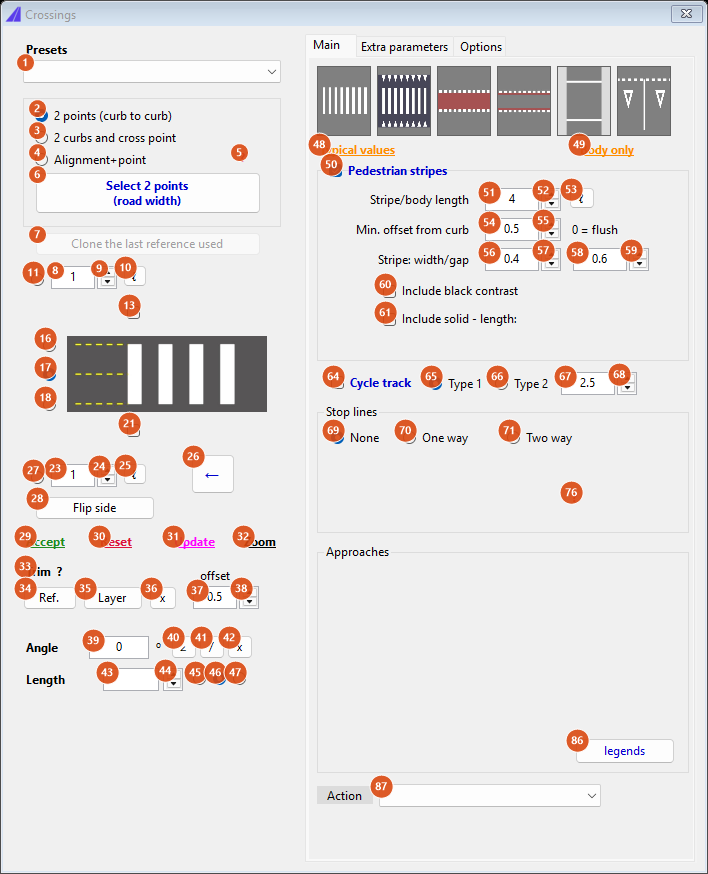
Default state: pedestrian stripes on, no stop lines. The left column is the same on every tab.
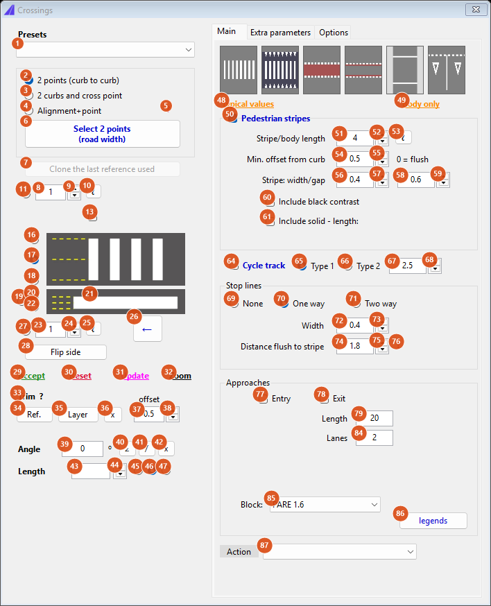
Stop lines "One way": the entry stop line is on, the stop line rows (72 to 76), the approach rows (77 to 79, 84, 85) and the entry stop-line anchors (19, 20, 22) appear.
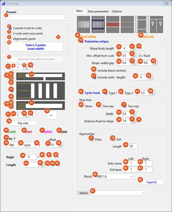
Stop lines "Two way" and "Include solid": both stop lines are on, the exit anchors (12, 14, 15) and the two-way lane boxes (80 to 83) appear, and the solid length (62) shows.
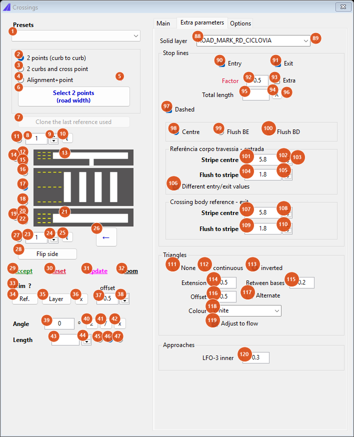
Extra parameters with both stop lines, Dashed, Different entry/exit values, inverted triangles and Include solid on, so every row is visible.
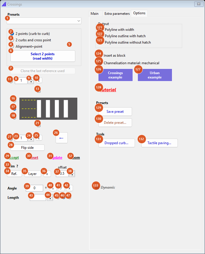
Options tab.
Presets and selection (left column, top)
| # | Control | What it does |
|---|---|---|
| 1 | Presets | Your saved presets first (alphabetical), then the built-in ones: Faixa de pedestres, Ciclovia padrão 1, Ciclovia padrão 2, Lombofaixa, Dê a preferência, Pedestres + ciclistas, Apenas retenções (see the table below). Selecting one loads its values and redraws. Type a new name here before Save preset (129). |
| 2 | 2 points (curb to curb) | Select asks for two points (Ponto 1 (guia), Ponto 2 (guia)), rubber-banded. The line between them is the reference. |
| 3 | 2 curbs and cross point | Select asks for exactly two kerb curves, then a point. A line transversal to the kerbs through that point becomes the reference. A selection that is not exactly two curves shows Select exactly 2 geometries. |
| 4 | Alignment+point | Select asks for an alignment (or any curve) and a point. The reference is the line transversal to the alignment at that point, as wide as the alignment's width, or 10 (5 each side) when it has none. |
| 5 | ? | Help for mode 4: A line transversal to the selected alignment will be created. If the selected alignment has a width applied, it will be used as reference. If not, the base value 10 is applied, and can be changed. |
| 6 | Select… | Hides the form and runs the pick chosen in 2 to 4. The caption follows the mode (Selecionar 2 pontos (largura via), Selecionar 2 bordos e ponto, Selecionar eixo e ponto). After the pick the reference line is drawn in magenta and the preview is generated. Picking a new line while a preview exists erases that preview first. |
| 7 | Clone the last reference used | Enabled after an Accept. Brings back the reference line you accepted last, resets the body and stop-line options ("Limpa valores": stripes, solid, cycle, triangles, stop lines and channelisation off, lanes at least 2) and redraws. Nothing stored: Not found. |
Built-in presets and what they set (all of them clear Different entry/exit values first):
| Preset | Sets |
|---|---|
| Faixa de pedestres | Stripes on; solid, cycle track, dashed stop line and triangles off. Stop lines are left as they are. |
| Lombofaixa | Stripes on, triangles inverted, colour white, Include solid with length 8 on the lombofaixa layer, then the typical values (with triangles on, the stripe-centre distance becomes 7 = 3 + 4). |
| Ciclovia padrão 1 / 2 | Stripes, solid and triangles off; cycle track on, Type 1 (red band) or Type 2 (red edge lines); cycle length 2.5; flush distance 2. |
| Dê a preferência | Typical values, stripes on, stop line Entry only, channelisation Entry only, Dashed with factor 0.4, direction One way, block DE_PREF_3.6. Shows once per session: Note that in this preset, stop line "at the entrance" and "one-way" approach were activated. |
| Pedestres + ciclistas | Applies the cycle preset and then ticks the stripes; because stripes and cycle track exclude each other, the result is stripes only, with the cycle preset's flush distance of 2. |
| Apenas retenções | Body off (stripes, solid, cycle, triangles), dashed off, stop lines Entry and Exit on. |
The six pictures at the top of the Main tab apply the same presets (left to right: Faixa de pedestres, Lombofaixa, Ciclovia padrão 1, Ciclovia padrão 2, Apenas retenções, Dê a preferência).
Anchor of the reference line (left column, picture strip)
The strip shows, from top to bottom, the exit stop line, the crossing body and the entry stop line; each picture appears only when that part is being drawn. The radio buttons beside them say which feature sits on the reference line you picked. Changing the anchor moves the whole marking; use ← (26) to move the line instead.
| # | Control | What it does |
|---|---|---|
| 11 | exit offset anchor | The reference line lies Exit offset (8) beyond the outer edge of the exit stop line. |
| 8, 9, 10 | Exit offset, ±, ℓ | The offset for anchor 11 (0 to 10, step 0.1). ℓ measures it in the drawing (base point, then distance) and selects anchor 11. Clicking into the box also selects anchor 11. |
| 12, 14, 15 | exit stop line: outer edge, middle, inner edge | The reference line lies on the far edge, the centre line or the near edge (towards the body) of the exit stop line. Shown only when the exit stop line is on. |
| 13 | exit stop line (mirror) | The same as Exit (91) on the Extra parameters tab: turns the exit stop line on or off. |
| 16, 17, 18 | body: exit edge, centre, entry edge | The reference line lies on the exit edge of the body, on its centre (default) or on its entry edge. Shown while a body (stripes, solid or cycle track) is drawn; centre also shows when both stop lines are on. |
| 20, 19, 22 | entry stop line: inner edge, middle, outer edge | As 12, 14, 15 for the entry stop line. |
| 21 | entry stop line (mirror) | The same as Entry (90). |
| 27 | entry offset anchor | The reference line lies Entry offset (23) before the outer edge of the entry stop line: use it to place the line on a give-way line or a kerb of the side street. |
| 23, 24, 25 | Entry offset, ±, ℓ | The offset for anchor 27, as 8 to 10. |
| 26 | ← | Moves the reference line from the anchor it was placed for to the anchor now selected, so the marking stays where it is and only the magenta line moves. Then redraws. |
| 28 | Flip side | Reverses the reference line: entry and exit swap sides, the stop lines and lanes follow. |
The selected anchor is remembered between sessions.
Actions, trim, angle and length (left column, bottom)
| # | Control | What it does |
|---|---|---|
| 29 | Accept (green) | Keeps the preview as ordinary entities, erases the magenta line, stores the line for Clone (7) and prints Elementos aceitos. The next preview starts fresh. |
| 30 | Reset (red) | Erases the last preview. The reference line and the values stay, so you can carry on. |
| 31 | Update (magenta) | Re-reads the magenta line from the drawing (you may have moved or stretched it), redraws it if you deleted it, and regenerates the preview, even with Dynamic off. |
| 32 | Zoom | Zooms to twice the extents of the reference line (Zoom Extents when there is none). |
| 33 | Trim ? | Help: Select geometries for trim; they will be considered closed even if open. They must also not cross each other. |
| 34 | Ref. | Pick one or more curves as the trim boundary. Everything drawn afterwards is clipped and only what is inside the boundary is kept; elements that do not touch it are kept whole. |
| 35 | Layer | Pick one entity: every entity on its layer becomes the boundary. More than 100 entities: Limit for entities in layer: 100. A boundary that would cross itself once closed: Selected geometries for trim are inconsistent… and nothing changes. |
| 36 | x | Forgets the boundary and redraws. |
| 37, 38 | offset, ± | Not available in this version: with a boundary loaded and a non-zero value the command line prints a warning and clips with the boundary as picked. |
| 39 | Angle | Skew of the crossing in degrees, applied when you press Enter. The value is folded to the nearest half turn, so −10 reads 350. The stripes, stop lines and lane lines are sheared by this angle. |
| 40 | ∠ | Measures the skew: base point, then direction. The direction is converted to the skew relative to the perpendicular of the reference line. |
| 41 | / | Pick a curve near a point: the skew becomes the curve's direction at the foot of the perpendicular from that point (within 10 units). No foot found: Angle in clicked point not found. |
| 42 | x | Sets the angle back to 0. |
| 43, 44 | Length, ± | Shows the length of the reference line. Type a new value and press Enter (or click ±, step 0.5) to lengthen or shorten the line to that total and redraw. Zero or negative values are ignored. |
| 45, 46, 47 | keep left / middle / right | Which part of the line stays put when the length changes: the first point, the middle (default) or the second point. |
Typing a non-zero angle while the output is Polyline with width (121) shows, once per session: For skewed situations, consider using the "polyline contours" output option instead of "polylines with width". with the buttons Ok and Swap; Swap jumps to the Options tab and selects Polyline outline with hatch.
Tab 1: Main, body of the crossing
| # | Control | What it does |
|---|---|---|
| 48 | Typical values | Loads the typical values and redraws (also with Dynamic off): stripes 4 long, 0.4 wide, gap 0.6, minimum offset from kerb 0.5; stop line 0.4 wide, stripe-centre distance 5.8 (7 when triangles are on); approach length 20, lanes 2, LFO-3 inner 0.3, block PARE 1.6; teeth extension 0.9 and offset 1. |
| 49 | Body only | Direction None, both stop lines off, redraw: the body alone. |
| 50 | Pedestrian stripes | Draws the zebra. Ticking it clears Cycle track (64) and the other way round. |
| 51, 52, 53 | Stripe/body length, ±, ℓ | Length of the stripes across the road, that is the width of the crossing (0.1 to 20, step 0.1). ℓ measures it in the drawing. Changing it also updates Stripe centre (101) = flush distance + length. |
| 54, 55 | Min. offset from curb, ± | Minimum space between each kerb and the first stripe (0 to 3, step 0.05). The stripe pattern is centred on the line and the space left over is shared between the two kerbs; when it falls short of this value it is enlarged in half-pattern steps. 0 = flush: the first stripe starts at the kerb. |
| 56, 57 | Stripe width, ± | Width of each white stripe along the reference line (0.05 to 5, step 0.05). |
| 58, 59 | gap, ± | Space between two stripes (0.05 to 5, step 0.05). |
| 60 | Include black contrast | Adds a black quad in every gap (layer of the black stripes) and patches the run so it ends on a black quad. |
| 61, 62, 63 | Include solid - length, value, ± | Adds a filled band under the body, this long across the road (1 to 20, step 0.1; 0 = same as the stripes), centred on the body, on the Solid layer (88). |
| 64 | Cycle track | Draws the cycle crossing instead of the zebra (the two exclude each other). Always with a dashed square stop line (0.4 squares) on both sides, 0.2 from the body. |
| 65 | Type 1 | The body is a red filled band (padrão 1). |
| 66 | Type 2 | The body is two red edge lines 0.1 wide instead of the band. |
| 67, 68 | cycle length, ± | Width of the cycle crossing across the road (1 to 10, step 0.1). Used as the body length while Cycle track is on. |
Tab 1: Main, Stop lines
| # | Control | What it does |
|---|---|---|
| 69 | None | No stop lines and no lanes (default). Turns Entry and Exit (90, 91) off. |
| 70 | One way | Turns the entry stop line on and the exit off. The stop line spans the whole road, the approach has the number of lanes in 84. |
| 71 | Two way | Turns both stop lines on. Each stop line spans only the lanes of its direction (the right-hand half seen from that direction); the double yellow line separates the two directions. |
| 72, 73 | Width, ± | Width of the stop line (0 to 1, step 0.05). Also the size of the dashed-line squares when Dashed is on. |
| 74, 75 | Distance flush to stripe, ± | Distance from the edge of the body to the near edge of the stop line (0 to 100, step 0.05). Mirrored by 104. |
| 76 | ? | Measured from the central stop line to the start of the crossing body. |
Tab 1: Main, Approaches
| # | Control | What it does |
|---|---|---|
| 77 | Entry | Draws the entry channelisation: lane lines and legends on the entry approach and, for two-way roads, the double yellow line. Also needed for the lane lines on the exit side of a two-way road. |
| 78 | Exit | Draws the exit channelisation (two-way roads): double yellow line and legends on the exit approach. |
| 79 | Length | Length of the lane lines and yellow lines, measured from the stop line away from the crossing. |
| 84 | Lanes (one way) | Number of lanes of the approach. Lane lines (LMS, 0.1 wide) are drawn between them and a legend is inserted in every lane. |
| 80, 81 | Entry lanes Left / Right | Two way: lanes on the entry side. Right = lanes travelling towards the crossing (the entry stop line covers them), Left = lanes of the opposite direction. 0 counts as 1. |
| 82, 83 | Exit lanes Left / Right | The same for the exit side, seen from the exit direction. 0 copies the entry values. |
| 85 | Block | Legend inserted in every lane before the stop line: empty (none), PARE 1.6, PARE 2.4, DE_PREF_3.6, or any block name you type. The block comes from the CapCad library on the manual white layer. |
| 86 | legends | Shows Add arrows and other elements with the "Conjunto Inscrições" (inscriptions set) command and runs CAPCAD_ROAD_SET_TRANSVERSAL. |
| 87 | Action | Action suffix for the layers of everything drawn: NEW, EXISTENT, TO REMOVE (Brazil: IMPLANTAR, MANTER, REMOVER, REVITALIZAR; urban profile: COL, EX, RET). Empty or the "new" value draws on the plain layers. See the note on the English values below. |
The LFO-3 inner value (120, Extra parameters) is the distance between the two yellow lines.
Tab 2: Extra parameters
| # | Control | What it does |
|---|---|---|
| 88 | Solid layer | Layer of the solid band (61): the red cycle-track layer or the lombofaixa layer of the active layer catalogue; any name can be typed. See the note below. |
| 89 | ? | Any layer name can be typed; CapCad system layers will be recognized and created, examples: SINA_HOR_AM, SINA_HOR_CANTEIRO etc... |
| 90, 91 | Entry, Exit | The entry and exit stop lines, the same as 21 and 13. |
| 97 | Dashed | The stop line becomes a row of squares (side = Width, 72) instead of a solid line; with Polyline with width output it is one polyline on the dashed layer SINA_HOR_BR_<factor>x<factor>_LRE. |
| 92 | Factor | Size of the squares and of the gaps between them. |
| 93 | Extra | Lengthens the dashed line by one more pattern (two squares). |
| 98 | Centre | The dashed line is lengthened equally at both ends to complete a whole number of squares, so the pattern is centred. |
| 99 | Flush BE | The squares are laid from the second point of the reference line (with Extra, the line is instead lengthened at its first point). |
| 100 | Flush BD | The squares are laid from the first point of the line; on the exit stop line it behaves like Flush BE. |
| 95 | Total length | Total length of the stop line, centred on the road; empty = as wide as the crossing. Use it with the entry stop line only (see Notes). |
| 94 | X | Clears Total length. |
| 96 | ? | If empty, the same extension as the crossing will be used. |
| 101, 102 | Stripe centre, ± | Flush distance + stripe length: the distance from the entry stop line to the exit edge of the body (0 to 100, step 0.05). Editing it recomputes Flush to stripe and the other way round. |
| 103 | ? | Measured from the central stop line to the start of the crossing body. |
| 104, 105 | Flush to stripe, ± | The same value as 74. |
| 106 | Different entry/exit values | Shows the exit group (107 to 110) and lets the exit stop line have its own distance; the exit values start as a copy of the entry ones. |
| 107, 108 | exit Stripe centre, ± | Exit counterpart of 101. |
| 109, 110 | exit Flush to stripe, ± | Distance from the body to the exit stop line. |
| 111 | None | No give-way teeth. |
| 112 | continuous | Teeth continuing from the stripe ends (European style): one triangle per stripe. |
| 113 | inverted | Teeth pointing at the crossing, placed in the gaps between stripes (lombofaixa, Brazil). |
| 114 | Extension | Height of the teeth. |
| 115 | Between bases | Inverted teeth only: gap between the bases of two neighbouring teeth. |
| 116 | Offset | Distance between the stripe ends and the base of the teeth. |
| 117 | Alternate | Keeps every other tooth. |
| 118 | Colour | White draws the teeth on the manual white layer, anything else on the manual yellow layer. |
| 119 | Adjust to flow | On (default): with One way and more than one lane the teeth are drawn on the entry side only; with Two way each side keeps the teeth only on the lanes that approach the crossing. Off: teeth on both sides, full width. |
| 120 | LFO-3 inner | Distance between the two lines of the double yellow line (two way). |
Tab 3: Options
| # | Control | What it does |
|---|---|---|
| 121 | Polyline with width | Every mark is a polyline with constant width (default). Dashes and squares come from the linetype of the layer; a skewed crossing loses its shear (see the advice above). |
| 122 | Polyline outline with hatch | Stripes, stop lines, teeth and bands are closed polylines drawn filled (2D solids). Dashed lines and cycle squares become real geometry. Use this for skewed crossings. |
| 123 | Polyline outline without hatch | Behaves like 122 (see Notes). |
| 124 | Insert as block | Not available in this version. |
| 125 | Channelisation material: mechanical | On (default): the lane lines (LMS) and the double yellow line (LFO-3) are drawn without the crossing's group id and type tag, so they stay independent of the crossing group. Off: they are tagged like the rest. |
| 126, 127 | Crossings example, Urban example | Sample file will be open - proceed? then opens the sample drawing (sample-travessias.dwg / sample-urbano.dwg). |
| 128 | Tutorial | Opens the video tutorial in the browser. |
| 129 | Save preset | Saves every remembered value (see below) under the name typed in 1 (Preset not set: when empty). Confirms with Preset |
| 130 | Delete preset... | Are you sure to delete: |
| 131 | Dropped curb... | Runs CAPCAD_ROAD_KERB_DROPPED. |
| 132 | Tactile paving... | Not available in this version. |
| 133 | Dynamic | On (default): every value change redraws. Off: only Update (31), Typical values (48), Body only (49), the Length box (43) and a new pick redraw. |
How the options combine
All figures were produced by running the command's own engine on a reference line 10 units long (one kerb at each end), with the output Polyline outline with hatch so that dashes and squares are visible, an approach length of 6 and no legend block unless stated. The magenta dashed line is the reference line as picked; the entry side is at the bottom of each picture. Colours follow the layers: white, black, yellow (LFO-3) and red (cycle track).
Body
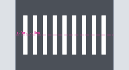
Default: stripes 4 long, 0.4 wide, 0.6 apart, at least 0.5 from each kerb, centred on the reference line (anchor 17). Here the leftover at each kerb is 0.8.
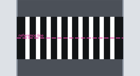
Include black contrast: a black quad fills every gap and the run ends on a black quad at both kerbs.
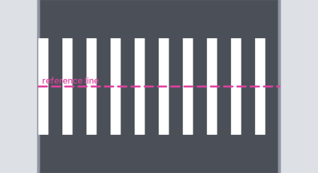
Min. offset from curb = 0: the first stripe starts at the kerb.
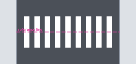
Stripe/body length 3, stripe width 0.5, gap 0.5.
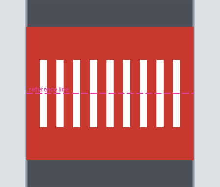
Include solid with length 8: a filled band 8 across, centred on the stripes. It is drawn on the cycle-track red layer (see Notes).
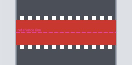
Cycle track, Type 1: red band 2.5 across and dashed square stop lines (0.4 squares) 0.2 from it on both sides.
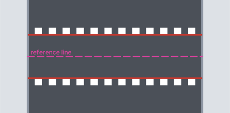
Cycle track, Type 2: red edge lines instead of the band.
Stop lines and approaches
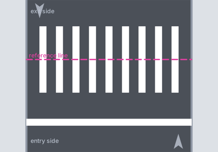
One way, entry stop line only (channelisation off): a line 0.4 wide, 1.8 before the body, across the whole road.
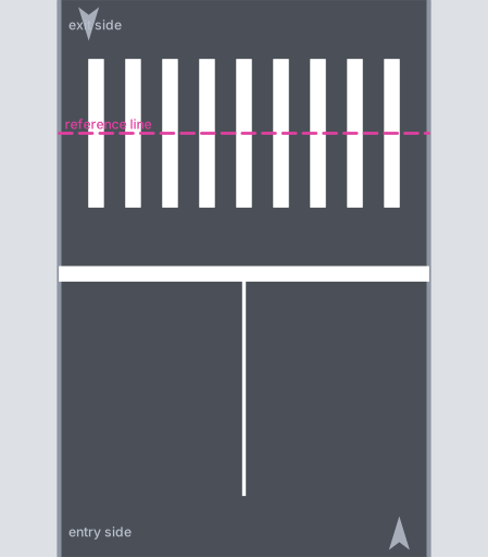
One way with Entry channelisation and 2 lanes: a lane line (LMS) 6 long between the lanes.
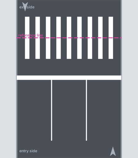
Lanes = 3: two lane lines.
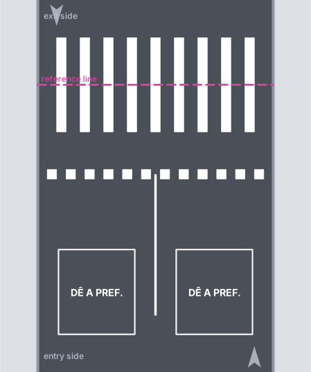
Block DE_PREF_3.6 with the Dashed stop line (factor 0.4), as the "Dê a preferência" preset sets it: one legend per lane, 5 units before the stop line. The rectangles mark where the library block is inserted.
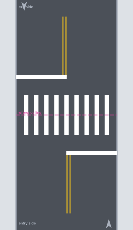
Two way with Entry and Exit channelisation, 1 + 1 lanes: each stop line covers its own direction, the double yellow line (0.3 apart) runs from each stop line away from the crossing.
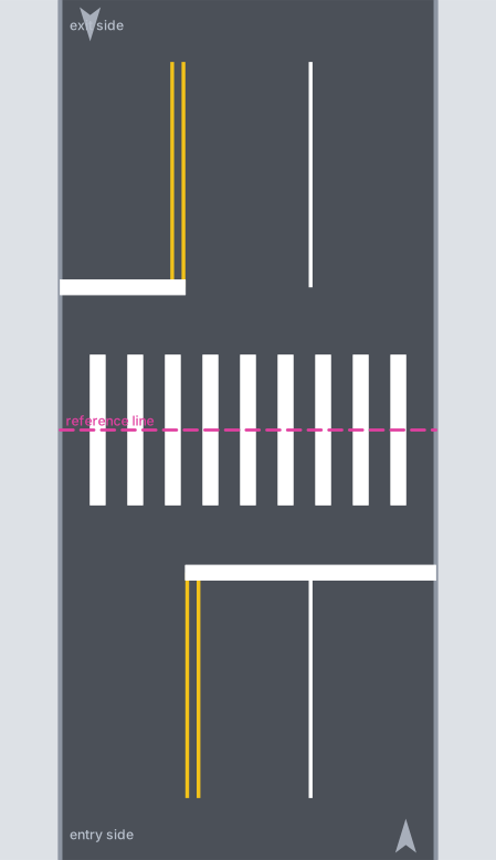
Two way, Entry lanes Left 1 / Right 2, Exit lanes Left 2 / Right 1: the entry stop line covers two lanes with a lane line between them; the lane line continues beyond the crossing on the exit side.
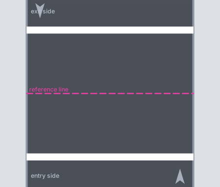
"Apenas retenções": no body, entry and exit stop lines 1.8 either side of where the body would be.
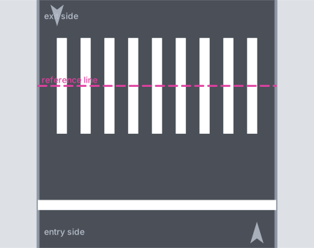
Distance flush to stripe = 3.
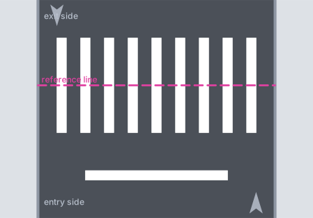
Total length = 6: the entry stop line is 6 long, centred on the road.
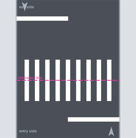
Different entry/exit values with the exit flush distance = 4: the exit stop line moves away from the body, the entry one stays at 1.8.
Dashed stop line
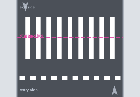
Dashed with factor 0.5, Centre: squares of 0.5, the line lengthened equally at both ends to complete the pattern.
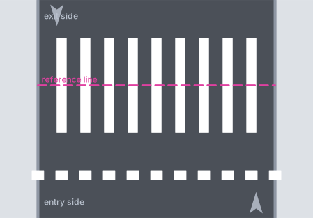
The same with Extra: one more pattern (two squares) is added.
Give-way teeth
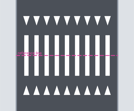
Triangles inverted, extension 0.9, offset 1: one tooth per gap, pointing at the crossing, on both sides (no stop lines, so Adjust to flow does nothing).
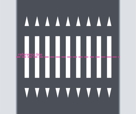
Triangles continuous: one tooth continuing each stripe.
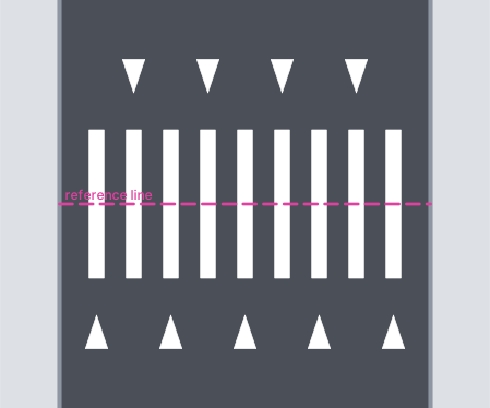
Alternate: every other tooth is dropped.
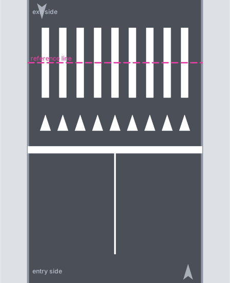
Adjust to flow with One way and 2 lanes: teeth on the entry side only (flush distance 3, as the Lombofaixa preset sets it).
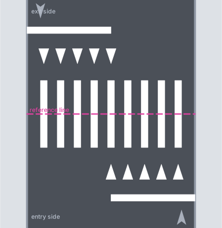
Adjust to flow with Two way: each side keeps the teeth on the lanes that approach the crossing.
Anchor
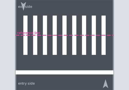
Anchor "centre" (17): the reference line is the centre line of the body.
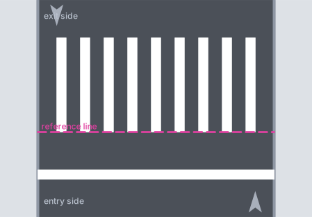
Anchor "entry edge of the body" (18): the stripes start on the reference line.
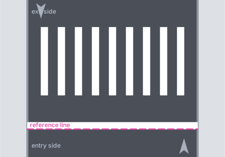
Anchor "outer edge of the entry stop line" (22): the stop line ends on the reference line and the body is 1.8 beyond it.
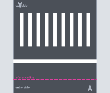
Anchor "entry offset" (27) with Entry offset = 2: the stop line starts 2 units after the reference line.
Skew
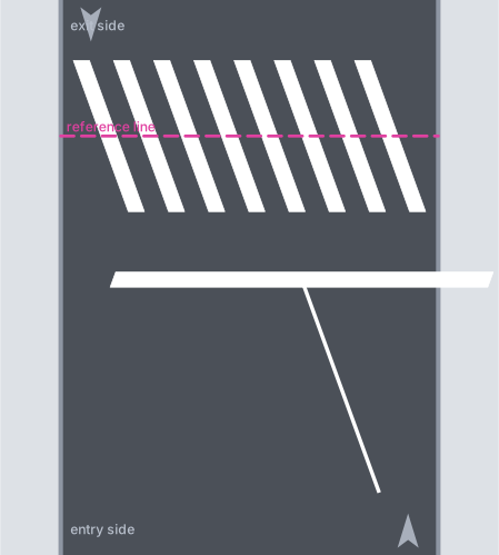
Angle = 20 with the outline output: stripes, stop line and lane line are sheared by 20 degrees.
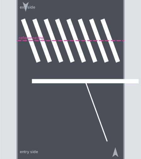
The same with "Polyline with width": each stripe is a rotated polyline with square ends and the stop line keeps its square ends, which is why the form suggests the outline output for skewed crossings.
Remembered between sessions
Saved when the form closes and restored when it opens; the same set is what a saved preset holds: entry and exit offsets (8, 23), trim offset (37), stripe length (51), solid length (62), stripe width and gap (56, 58), minimum offset from kerb (54), stop line width (72), stripe centre entry and exit (101, 107), approach length (79), one-way lanes (84), two-way lanes (80 to 83), triangle colour (118), solid layer (88), teeth extension, offset and gap (114 to 116), black contrast (60), stop lines entry and exit (90, 91), channelisation entry and exit (77, 78), direction (69 to 71), triangles inverted (113), block (85), dashed (97), stripes (50), solid (61), cycle track (64), anchor (11 to 27) and output (121 to 123).
Not remembered: angle, trim boundary, action, dashed factor and reference, total length, LFO-3 inner, cycle type and length, alternate, adjust to flow, material, dynamic.
User presets are saved for the user.
Notes
- Layers. Stripes
SINA_HOR_BR_FTP, black contrastSINA_HOR_PR_FTP, stop lineSINA_HOR_BR_LRE(dashed with width output:SINA_HOR_BR_<f>x<f>_LRE), lane linesSINA_HOR_BR_LMS1(between lanes of the same direction) andSINA_HOR_BR_2x4_LMS2, double yellowSINA_HOR_AM_LFO3(0.1 wide), teethSINA_HOR_BR_MANUALorSINA_HOR_AM_MANUAL, cycle trackSINA_HOR_VM_CICLOVIA, legend blocksSINA_HOR_BR_MANUAL. The names follow the active country profile. Every element carries the type tagTRAVESSIA-<type>(FAIXA BRANCA,FAIXA PRETA,LRE,LMS,LFO3,LOMBOFAIXA-DENTE,PINTURA VERMELHA…) and a group id per pass. - Solid layer (88). In this version the solid band is always created on the cycle-track red layer, whichever entry you choose; this also applies to the Lombofaixa preset.
- PARE legends. With
PARE 1.6andPARE 2.4the block is inserted centred on the stop line;DE_PREF_3.6and typed block names are inserted 5 units before the line. - Total length (95) is meant for the entry stop line alone: use it without an exit stop line.
- Action (87) in the English profile: with
NEW,EXISTENTandTO REMOVEthe layers are drawn without suffix whichever you choose. The Brazilian values (MANTER,REMOVER,REVITALIZAR,EX,RET) add the suffix. - Output 123 (outline without hatch) draws exactly what 122 draws.
- Command-line prompts of this command (
Ponto 1 (guia):,Selecione os 2 bordos, depois o ponto:, …) are in Portuguese in every language. - The reference line is only a guide: it is erased on Accept and when the form closes; the marking always stays.
- For a UK zebra crossing to TSRGD (Belisha layout with give-way and stud lines) use Crossings (simplified),
CAPCAD_MARKING_CROSSING_TSRGD.