| Command | CAPCAD_MARKING_AREA_2FLOW |
| Shortcut | Z2 (also ZB) |
| Ribbon | CapCad tab › Traffic Control panel › Area Marking split button › 2 Flows (tooltip Chevrons: 2 Flows) |
| Category | Horizontal: specials |
| Form | ChevronForm (modeless: the drawing stays live while it is open) |
| Hosts | AutoCAD, BricsCAD, GstarCAD, ZWCAD, ARES Commander |
| Also | Siblings, documented on their own pages: CAPCAD_MARKING_AREA_1FLOW (one reference line), CAPCAD_MARKING_AREA_3FLOW (three flows), CAPCAD_MARKING_AREA_LINEAR (along an axis) and CAPCAD_MARKING_AREA_ASSISTANT (picks the right one for your selection and opens this form with the references already loaded). CAPCAD_MARKING_HUB docks this form in the horizontal-marking hub; the Airport tools launch it by name. |
Draw a channelising island in seconds, to the norm, and keep adjusting it while you watch. With plain CAD commands a gore area is an afternoon of offsets, arrays, trims and hatches that you redo every time the geometry moves. Here you pick the two lines and everything else follows.
- Live preview. Every value you change redraws the whole island: strips, channelising lines, studs, contrast backing. Accept when it looks right, Reset if it does not.
- The norm's numbers, built in. Country presets carry the clear gap, strip width, line width, angle and gap of the UK TSRGD, France, Spain, Portugal, SIECA, Mexico, Colombia, Ecuador, Argentina, Paraguay and Ontario. Save your own presets for the user or the project.
- Four families, two methods. Merge and diverge (white V strips) or off-side and near-side (yellow diagonals), measured from a centre line or set at 45° to each channelising line (the reference method).
- Studs and delineators placed for you. Studs, big studs or delineators along both lines, with visibility, alternation and inner guide studs along each V.
- Simplified or detailed. Wide polylines for quick work at small scales, or closed outlines filled with hatch that honour the gap exactly, with a solid tip where the norm asks for one.
- Editable afterwards. Every island is tagged as a group and keeps the settings it was built with, so you can re-select it later and reopen it in the form to change it.
What it does
You pick two reference lines that meet at a point (the bico, the nose of the island) and open away from it. The command fills the wedge between them with chevron strips (white, for flows in the same direction: merge or diverge) or diagonal strips (yellow, for opposite flows: off-side or near-side), redraws the two references as channelising lines of the width you set, and places studs along them. Everything is drawn on the CapCad layers of the chosen colour, tagged as one group, and the settings are kept with the drawing.
The picture on the form is a live preview: each change erases the previous result and draws it again. Accept keeps it and lets you start another; Reset erases it; closing the form keeps the last preview in the drawing.
Typical uses: gore areas at ramp entries and exits, painted islands at junctions, the neutral area between diverging lanes, the striped zone before an obstacle in the carriageway.
Workflow
- Run
CAPCAD_MARKING_AREA_2FLOW(or typeZ2). The form opens beside the drawing. - Pick the family (8 to 11): merge or diverge for same-direction flows, off-side or near-side for opposite flows.
- Pick a Preset (57) if the country rule you need is listed, or type the clear gap, strip width and line width (18, 20, 22).
- Click Select reference (1) and pick the two lines. They should share an end point at the nose; one polyline with exactly two segments is also accepted and split at its middle vertex.
- The island appears. Refine: Start at (27), Extend mode (19), studs (33 to 45), Trim (23) against a boundary, Contrast (29), the angle and method (71 to 74).
- Click Accept (12). The result stays; the form is ready for the next pair of lines.
- To change an island later, click Edit existing (7) and pick any piece of it.
In AutoCAD each redraw is one undo step, so U removes the last preview only.
The form
Numbers are the same in every screenshot of this page. The Preset, Extras and Method groups sit under the tabs and are visible on both tabs; the "!" mark (66) only appears when a gap is typed in Simplified mode.
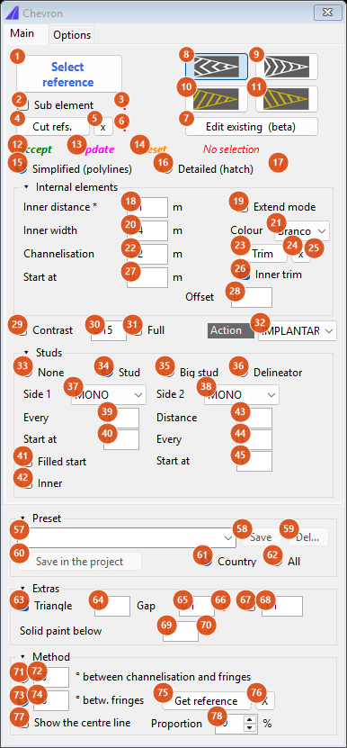
Tab "Main" as it opens in an English profile: Merge, Simplified, 1.10 / 0.40 / 0.20, studs on both sides, Triangle on with a 0.10 gap (a Brazilian profile opens with the triangle off and no gap).
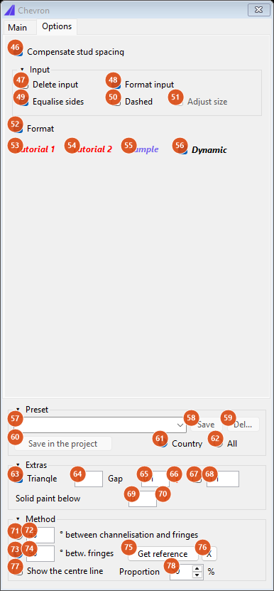
Tab "Options": input handling, formatting, the UK dashed-line pair, the tutorials and the sample drawing.
Tab "Main": selection and actions
| # | Control | What it does |
|---|---|---|
| 1 | Select reference | Hides the form and asks for the two reference lines. Exactly two curves are accepted; one polyline with exactly two segments (three vertices) is split at its middle vertex into the two references. Each line must be at most 2000 units long and have at most 30 segments. A new selection starts a new island: the previous preview stays in the drawing and stops being part of the preview. With Delete input (47) on, the picked entities are erased. |
| 2 | Sub element | Pick by segment instead of by entity: you click an entity near a segment, twice, and only the clicked segment of each is used as a reference. Delete input is ignored in this mode. |
| 3 | ? | Help: "Select 2 touching bits of a polyline." |
| 4 | Cut refs. | With the references selected, pick cut points (Esc to finish). Each point shortens the reference it is closest to, keeping the stretch from that reference's first vertex to the cut point, so the island stops there. Needs the references first ("Select the references first."). |
| 5 | x | Forget the cut points and redraw. |
| 6 | ? | Help: "Select 1 or 2 reference points to decrease hatched area." |
| 7 | Edit existing (beta) | Pick an island already in the drawing (any piece of it). Its stored settings and references are loaded onto the form, the old entities (and their contrast backing) are erased, and the island is redrawn under the same group identity, ready to be changed. Needs Dynamic (56) on, and a CAD that stores group records (AutoCAD). |
| 8 | Merge | White family: nested V strips between the two lines (see the figures below). |
| 9 | Diverge | White family: V strips the other way round; stud blocks are rotated 180°. |
| 10 | Off side | Yellow family: single diagonal strips leaning one way. The reference method (71) is never used for yellows. |
| 11 | Near side | Yellow family: the mirror image of Off side. |
| 12 | Accept (green) | Keep the preview as ordinary entities, forget the references, trim boundary and cut points, and wait for the next selection ("Accepted. Select new references."). The next island gets a new group identity. |
| 13 | Update (magenta) | Redraw the preview with the current values (also what Enter does in any value box). |
| 14 | Reset (orange) | Erase the preview. |
| 15 | Simplified (polylines) | Each strip is an open polyline with a constant width; the channelising lines are the two references drawn with the line width (22). |
| 16 | Detailed (hatch) | Each strip is a closed outline filled with a SOLID hatch, its ends following the references at exactly the gap (65); the two channelising lines become one closed filled band. The bico triangle (63) is filled in both modes. |
| 17 | ? | Help: "Detailed mode draws the internal fringes precisely as a closed polyline filled with hatch. Simplified draws open polylines with width. Simplified mode is recommended for scales of 1:500 or smaller." |
| status line | Red No selection until two references are picked; blue N strip(s). after a redraw; red text when something stops the preview |
Tab "Main": Internal elements
| # | Control | What it does |
|---|---|---|
| 18 | Inner distance * (m) | The clear gap between two strips, measured perpendicular to them: the number the norms quote. The strip width is added and the result converted to the pitch along the centre line (÷ sin(angle/2), which is ×√2 at 90°) or along the references (×√2 in the reference method). Applied when you press Enter. |
| 19 | Extend mode | Lengthen the references in memory before dividing (×1.1 merge, ×1.25 diverge, ×1.75 yellows) so the last strips reach past the open end instead of stopping short of it. Switched off automatically when the two lines do not touch at the nose. |
| 20 | Inner width (m) | Width of each strip. A value above 5 is taken as centimetres and divided by 100. Below 0.01 the status line says "Internal width too small.". |
| 21 | Colour | Branco (white), Amarelo (yellow), Azul, Vermelho, Verde, Preto. Picks the CapCad layers of the active layer catalogue: white and yellow have one layer for the strips (…_ZPA) and one for the channelising lines (…_LCA); blue, red, green and black use their single colour layer for both. The list is not translated. |
| 22 | Channelisation (m) | Width of the two channelising lines drawn over the references when Format input (48) is on, and of the inset the Detailed strips keep from them. It also enters the stud offset (half of it, plus 0.10, plus the stud half-depth of 0.20). Below 0.01 the status line says "External width too small.". |
| 23 | Trim | Pick one curve as a trim boundary. It is treated as closed even if it is not. |
| 24 | x | Forget the trim boundary. |
| 25 | ? | Help: "Select a trim geometry reference, will be considered as closed even if it isn't." |
| 26 | Inner trim | On (default): the part of every strip inside the boundary is removed, the outside is kept. Off: the inside is kept. Strips the boundary does not touch are kept either way. |
| 27 | Start at (m) | Distance skipped along the centre line before the first strip. Only in the official method (73); the box is disabled with the reference method. |
| 28 | Offset | Moves the trim boundary by this distance before trimming (closed boundaries only); the direction flips with Inner trim. 0 = trim on the boundary itself. |
Tab "Main": Contrast and Action
| # | Control | What it does |
|---|---|---|
| 29 | Contrast | Draw a black backing behind the strips: every open strip is repeated with its width plus the value in 30, on the black layer, behind the island. Closed strips (Detailed mode) are skipped, so in Detailed mode this needs Full. The backing has its own group identity, so Edit existing erases it with the island. |
| 30 | value | How much wider the backing is than the strip (default 0.15). |
| 31 | Full | Instead of one halo per strip, one closed backing over the whole island: the two references joined and closed with a straight line. Part of the island's own group. |
| 32 | Action | IMPLANTAR (new work, no suffix), MANTER, REMOVER or REVITALIZAR: adds the corresponding suffix to every layer used (strips, channelising lines, contrast, studs), so the entities pick up the domain colour of that action. |
Tab "Main": Studs
Studs are library blocks inserted along the two references, offset outwards from the line, and rotated with the line. They need a CAD that inserts preview blocks (AutoCAD); the other hosts silently skip them.
| # | Control | What it does |
|---|---|---|
| 33 | None | No studs. |
| 34 | Stud | Block TACHA (default). |
| 35 | Big stud | Block TACHAO. The studs move to the yellow strips layer. |
| 36 | Delineator | Block BALIZA. |
| 37 | Side 1 | Visibility state of the blocks along reference 1: SEM (no studs on this side), MONO, BI, MONO_PLOTAVEL, BI_PLOTAVEL, GENERICA_VAZADO, GENERICA_PREENCHIDO. Written to the block's Visibility1 property. |
| 38 | Side 2 | The same for reference 2. |
| 39 | Every | Keep one stud every N positions, counted from Start at (40). 1 = every stud. |
| 40 | Start at | Position (1-based) of the first stud kept. |
| 41 | Filled start | Also keep the positions before Start at, so the alternation begins there without a gap at the nose. Shared with the inner studs. |
| 42 | Inner | Also place guide studs along each V, from the stud on reference 1 to the apex and down to the stud on reference 2. Needs a distance in 43. |
| 43 | Distance | Spacing of the inner studs along the V. Empty or 0 = no inner studs. |
| 44 | Every (inner) | Generate inner studs on every Nth V. |
| 45 | Start at (inner) | First V (1-based) that receives inner studs; Filled start (41) also fills the Vs before it. |
Where a stud lands on its stretch of reference (between two strip contacts) depends on Compensate stud spacing (46): with it, the stud sits at half, one third or two thirds of the stretch according to the strip angle; without it, always in the middle.
Tab "Options"
| # | Control | What it does |
|---|---|---|
| 46 | Compensate stud spacing | On (default): studs are placed at ½, ⅓ or ⅔ of their stretch of reference according to the angle of the strips, so they sit visually between the strips. Off: every stud in the middle of its stretch (see figure). |
| 47 | Delete input | Erase the two picked references after selecting them (the channelising lines drawn by Format input replace them). Not applied in Sub element mode. |
| 48 | Format input | Redraw the two references as channelising lines with the width in 22 on the …_LCA layer (Detailed: one closed filled band). Off: the references are left as they are and nothing is drawn over them. Gate for Dashed. |
| 49 | Equalise sides | Not available in this version. |
| 50 | Dashed | United Kingdom profile only, with Format input on: the channelising lines go on the …_ZPA_1004 layer, which carries the TSRGD "1004" dashed linetype loaded from TSRGD plus.lin (diagram 1041). Elsewhere the lines stay on the plain layer. Enabled only while Format input is on. |
| 51 | Adjust size | With Dashed: stretch each channelising line so it starts and ends on a whole dash. If the pattern cannot be read the line is drawn unadjusted and the status says "Dashed pattern not found on |
| 52 | Format | On (default): draw on the CapCad layers described above. Off: everything goes on the current layer. |
| 53, 54 | Tutorial 1, Tutorial 2 | Open the video tutorials (Brazilian profile only; other profiles get "Under development."). |
| 55 | Sample | After "Sample file will be open - proceed?", downloads sample-chevron-2.dwg from the CapCad server and opens it. |
| 56 | Dynamic | Live preview. Off: changes are not drawn until you switch it back on (and Edit existing refuses to run). |
Preset (under the tabs)
| # | Control | What it does |
|---|---|---|
| 57 | Preset | In this order: presets saved in the project (prefixed project:), presets saved for the user, then the built-in country rules. Picking one applies it and redraws; typing a new name is how you create a preset (only Save/Del... react while you type). A built-in that has no values says "Under development." and changes nothing. |
| 58 | Save | Save the current values under the typed name in the user file (Exports\presets.config). Disabled on built-in names. Asks before overwriting; confirms with "name preset recorded.". |
| 59 | Del... | Delete the custom preset shown, after "Are you sure to delete: name ?"; confirms with "Preset deleted: name". |
| 60 | Save in the project | Save into the project's presets.config (project root, or its presets folder when the project names one). Enabled only when a project is open and the name is custom. |
| 61 | Country | List only the built-ins of the active country profile (default). |
| 62 | All | List every country's built-ins, for comparison and testing. |
A preset carries: inner distance, widths, angles, method, Simplified/Detailed, format input, dashed, adjust size, extend, delete input, triangle on/size, gap, solid paint width, stud family, chevron family and colour. Applying one first sets the internal angle to 90° and then the preset's own values, and a preset that carries a gap switches the form to Detailed, because only that mode draws the gap exactly. Contrast, trim, action and the stud filters are not part of a preset.
Built-in presets and what they set (widths and gaps in metres; blank = the preset leaves that box alone):
| Preset | Profiles | Inner distance | Inner width | Channelisation | Gap | Angle | Method | Studs | Extras |
|---|---|---|---|---|---|---|---|---|---|
| UK-TSRGD-MOTORWAY | uk, generic | 1.40 | 1.00 | 0.20 | 0.15 | 90 | official | none | triangle 2 |
| UK-TSRGD-1041 (tipo 1) | uk, generic | 2.02 | 0.10 | 0.15 | 0 | 90 | official | none | triangle 1, format input, dashed, adjust size |
| UK-TSRGD-1041 (tipo 2) | uk, generic | 1.26 | 0.15 | 0.20 | 0 | 90 | official | none | triangle 1, format input, dashed, adjust size |
| USA-FHWA | usa | 0.30 | 90 | official | none | white | |||
| USA-FHWA-URBAN | usa | 0.20 | 90 | official | none | white | |||
| CANADA-ONTARIO | canada | 3.79 | 0.45 | 90 | official | none | white | ||
| CANADA-ONTARIO-URBAN | canada | 1.67 | 0.45 | 90 | official | none | white | ||
| ARGENTINA-CARRETERAS | argentina | 0.80 | 0.40 | 0.10 | official | none | |||
| ARGENTINA-URBANO | argentina | 0.40 | 0.40 | 0.10 | official | none | |||
| CHILE | chile | 1.00 | 0.40 | 0.20 | 0.15 | 90 | official | none | Detailed, Diverge, white |
| CHILE-URBANO? | chile | 2.50 | 0.15 | 0.20 | 0.15 | 90 | official | none | triangle 1, format input, dashed, adjust size, white |
| COLOMBIA-CARRETERAS | colombia | 2.00 | 1.00 | 0.30 | 90 | official | none | white | |
| COLOMBIA-URBANO | colombia | 1.20 | 0.60 | 0.20 | 90 | official | none | white | |
| ECUADOR-CARRETERAS | ecuador | 2.00 | 1.00 | 0.15 | 0.15 | 90 | official | none | |
| ECUADOR-URBANO | ecuador | 1.20 | 0.60 | 0.10 | 0.10 | 90 | official | none | |
| PORTUGAL-AUTOESTRADA | portugal | 1.50 | 0.50 | 0.20 | 0.30 | 53.13 | official | none | white |
| PORTUGAL-ESTRADA | portugal | 1.00 | 0.30 | 0.15 | 0.30 | 53.13 | official | none | white |
| PARAGUAY-CARRETERAS, -URBANO | paraguay | 1.00 | 0.40 | 0.30 | 0 | 60 | official | none | white |
| MEXICO-CARRETERAS | mexico | 2.00 | 0.20 | 0.15 | 90 | official | none | white | |
| MEXICO-URBANO | mexico | 2.00 | 0.10 | 0.10 | 90 | official | none | white | |
| SIECA-CARRETERAS | sieca | 2.50 | 1.00 | 0.20 | 0.20 | 53.13 | official | none | triangle 2, Detailed |
| SIECA-URBANO | sieca | 1.00 | 0.40 | 0.20 | 0.20 | 53.13 | official | none | triangle 2, Detailed |
| FRANCE-AUTOROUTE / -ROUTE / -URBAIN | france | 1.35 | 0.50 | 0.225 / 0.18 / 0.15 | 0.15 / 0.12 / 0.10 | 53.13 | official | none | white, solid paint below 0.30 |
| SPAIN-CARRETERAS | spain | 2.50 | 1.00 | 53.13 | official | none | Detailed, white, solid paint below 1.00 | ||
| SPAIN-URBANO | spain | 1.00 | 0.40 | 53.13 | official | none | Detailed, white, solid paint below 1.00 |
The presets of the Brazilian profiles are listed on the Portuguese page.
Every preset that sets anything also resets Solid paint below to 0 unless it states its own value. Listed but without values ("Under development."): EUROPE-GENERAL-HIGHWAY, BOLIVIA, PERÚ, URUGUAY and VENEZUELA (carreteras and urbano).
Extras (under the tabs)
| # | Control | What it does |
|---|---|---|
| 63 | Triangle | Draw a filled triangle at the nose, closing the tip of the island. |
| 64 | value | Length of the triangle's legs along each reference. |
| 65 | Gap | Space left between each strip end and the channelising line. Simplified: each strip is shortened by this much at both ends (a strip shorter than twice the gap is dropped). Detailed: the outline is built against the references inset by half the line width plus the gap, so the gap is exact. Default 0.10 in an English profile, 0 in a Brazilian one. |
| 66 | ! | Shown when a gap is typed in Simplified mode. Click it for the explanation: "The gap between the strip and the channelizing line is only exact in Detalhado (hatch) mode. In Simplificado the strip is a constant-width polyline whose flat end cap sits half a width past the geometric end, so the gap that reaches the drawing is smaller than the one typed. Use Detalhado to honour the norm." |
| 67 | (check box) | Enable a second spacing for reference 2. Reference method and Simplified mode only (Detailed ignores it). |
| 68 | value | The second spacing: reference 2 is divided every this much instead of every Inner distance. The strips pair the two sides sample by sample. |
| 69 | Solid paint below (m) | Width of the wedge, measured across it, below which the strips are replaced by one solid filled area at the tip. France asks for 0.30, Spain for 1.00; 0 = off. |
| 70 | ? | Help: "Where the wedge gets too narrow, the norm replaces the pattern with SOLID paint. Type the width (in metres, measured across the wedge) below which that applies: strips narrower than it are dropped and the tip becomes one filled area. France (IISR art. 117-2): below 0.30 m. Spain (8.2-IC): below 1.00 m. 0 turns it off, which is what every other norm uses." |
Method (under the tabs)
| # | Control | What it does |
|---|---|---|
| 71 | (radio) ° between channelisation and fringes | The reference method: each reference is divided along its own length and the strips leave the channelising lines at the angle in 72 (45°), meeting in a V. White families only: for yellows it is silently replaced by the official method, and so it is when both ends of the references coincide, or neither does (a closed or rectangular layout). If no V can be formed, the command tries once more with the sides swapped. Where only one side has samples left, nothing is drawn there. |
| 72 | value | The angle between channelising line and strip in the reference method. |
| 73 | (radio) ° betw. fringes | The official (centre-line) method, default: a centre line is averaged between the two references, divided at the pitch, and from each division a strip is cast to each reference at half the angle in 74. Used by every country preset except the Brazilian ones. |
| 74 | value | The angle between the two legs of each strip: 90 for the 45° family (Brazil CET, UK, USA, Colombia, Chile, Mexico, Ecuador, Canada), 53.13 for the 2:1 family (France, Spain, Portugal, SIECA), 60 for Paraguay. Must be between 15° and 120°, otherwise "Internal angle must be between 15° and 120°." and nothing is drawn. Every preset sets it. |
| 75 | Get reference | Pick your own centre line instead of the averaged one. Proportion no longer applies. |
| 76 | X | Drop the picked centre line and go back to the averaged one. |
| 77 | Show the centre line | Also draw the centre line used (picked or averaged) on the auxiliary layer CAPCAD_AUX_1. |
| 78 | Proportion (%) | Where the averaged centre line runs between the references: 0 on reference 1, 100 on reference 2, 50 in the middle. |
How the options combine
All figures below were produced by running the command's own engine on a sample wedge 22 m long and 4.4 m wide at the open end. Channelising lines are drawn with the Channelisation width, strips with the Inner width; orange dots are the studs on reference 1, blue dots on reference 2.
The four families
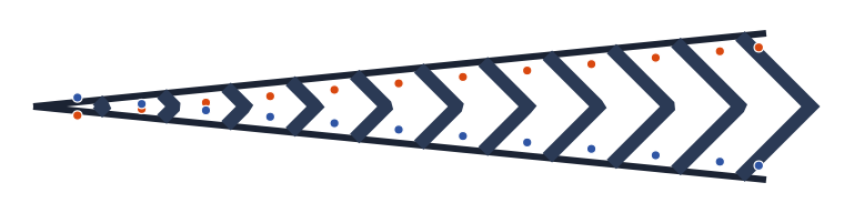
Merge, form defaults (official method, 90° between strips, 1.10 / 0.40 / 0.20): 11 V strips, one stud per stretch on each side.
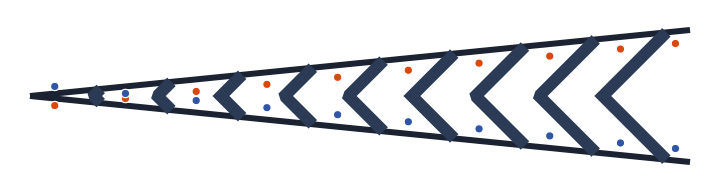
Diverge, the same values: the Vs point the other way (stud blocks are also turned 180°).
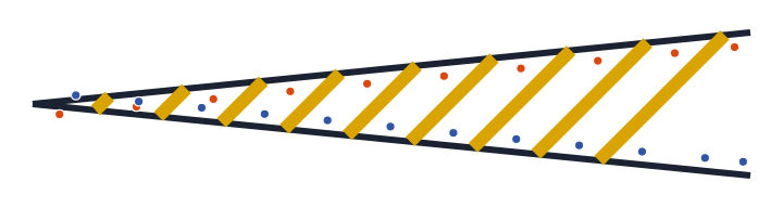
Off side (yellow): single diagonal strips.
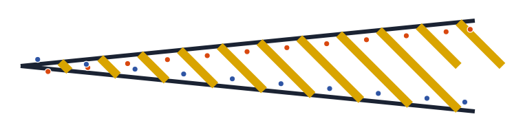
Near side (yellow): the mirror image.
Centre-line method versus reference method
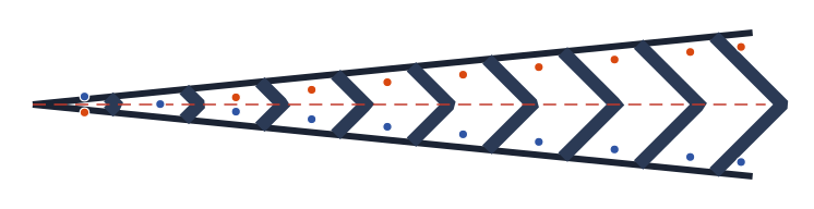
Official (centre-line) method with 1.40 / 0.40 / 0.20: the centre line (dashed red) is divided at the pitch and each strip leaves it at 45° to both sides.
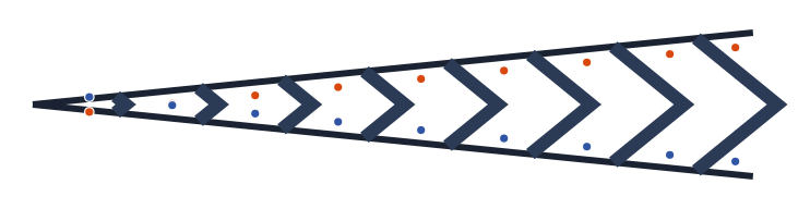
The same values with the reference method: the references themselves are divided and the strips leave them at 45°.
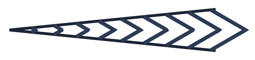
Angle 60° between strips (the Paraguay presets, 1.00 / 0.40 / 0.30): the Vs close up and the pitch grows (÷ sin 30°).
Start at, Proportion, Extend mode
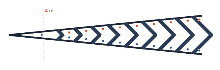
Start at = 4: the first 4 m of the centre line get no strip.
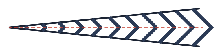
Proportion 50 %: the centre line runs midway between the references (Show the centre line on).
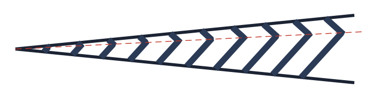
Proportion 25 %: the centre line leans towards reference 1, and the strips' apexes with it.
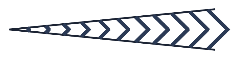
Extend mode off: the strips stop where the references stop.
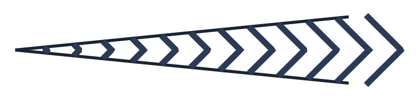
Extend mode on: the references are lengthened in memory (×1.1 for merge) and one more strip is cast past the open end.
Triangle, gap, Detailed mode
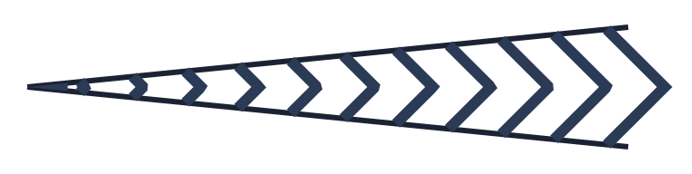
Triangle with legs of 1.5 m: a filled triangle closes the nose.
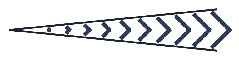
Gap 0.30 in Simplified mode: each polyline is shortened by 0.30 at both ends, but its flat end cap still reaches half a width closer to the line; the first strip, shorter than twice the gap, disappears.
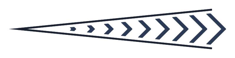
The same gap 0.30 in Detailed mode: closed outlines whose ends follow the references at exactly 0.30 from the channelising line.
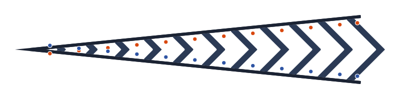
Detailed mode with the form defaults: filled strips and the channelising lines as one filled band.
Country presets

UK-TSRGD-MOTORWAY on a 26 m wedge: 1.00 m strips, 1.40 clear gap, 0.15 gap to the edge line (so Detailed), triangle of 2 m, no studs.

FRANCE-AUTOROUTE: 0.50 strips at 53.13° between the legs, 1.35 clear gap, 3u = 0.225 lines, 2u = 0.15 gap, and solid paint where the wedge is narrower than 0.30 m: the two narrowest strips are replaced by one filled tip.
Studs
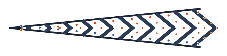
Inner studs every 1.0 m (reference method): guide studs run from each side stud to the apex of its V.
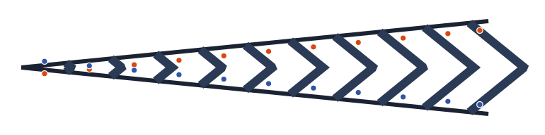
Compensate stud spacing off: every stud in the middle of its stretch of reference (compare with the reference-method figure above, where they sit at a third).
References that do not touch
The two lines do not share an end point: the nearest ends are paired, Extend mode is disabled and the status line adds "Lines do not touch — nearest ends paired.".
Remembered between sessions
Saved when the form closes and restored when it opens: inner distance, inner width, channelisation width, both angles, Simplified/Detailed, method, Format input, Dashed, Adjust size, Triangle and its size, Delete input and Extend mode. The remaining controls open with their defaults (which differ by profile: an English profile opens with the triangle on and a 0.10 gap, a Brazilian one with neither).
Custom presets live in Exports\presets.config (user) and in the project's presets.config.
Each island keeps a build record in the drawing (its references, trim boundary, centre line, cut points and every control value), which is what Edit existing reads back.
Notes
- The sibling commands share the same country rules:
CAPCAD_MARKING_AREA_1FLOWhatches one side of a single line,CAPCAD_MARKING_AREA_3FLOWfills the area between three lines,CAPCAD_MARKING_AREA_LINEARruns chevrons along an axis, andCAPCAD_MARKING_AREA_ASSISTANTlooks at your selection and opens the right one, this form included, with the lines already loaded. Each has its own page. - Every entity drawn (strips, channelising lines, studs, contrast, triangle) carries the island's group id and the type
ZEBRADO, soCAPCAD_SELECT_GROUPpicks the whole island from any piece of it. The preview keeps rewriting the same group until you Accept or select new references. - The channelising lines are drawn on the
…_ZPA(strips) layer when Dashed applies, and on the…_LCAlayer otherwise; the Action suffix is applied to both. - The inner distance is the clear gap perpendicular to the strips, which is how most norms quote it. The UK and Ontario quote the spacing along the axis; their presets already carry the converted value.
- The list under Colour shows the Portuguese colour names in every language, and the Action list shows the Portuguese layer-suffix words; both are as they appear on the form today.
- Blue, red, green and black draw strips and channelising lines on one and the same layer.