| Command | CAPCAD_MARKING_AREA_1FLOW |
| Shortcut | Z1 |
| Ribbon | CapCad tab › Traffic Control panel › Area Marking split button › 1 Flow (tooltip Chevrons: 1 Flow) |
| Category | NEW |
| Form | OneSideForm (modeless: the drawing stays live while it is open) |
| Hosts | AutoCAD, ARES Commander |
| Also opened by | CAPCAD_MARKING_AREA_ASSISTANT (one entity selected, answer 1 side); CAPCAD_MARKING_HUB docks the same tool as the Zebrado 1 lado panel |
Hatch one side of a line and watch it redraw as you type. Drawing a zebrado by hand means offsetting, arraying, trimming and re-doing it all when the spacing changes. This tool draws the stubs from one reference line and keeps them live.
- One line is enough. Pick a line, polyline or arc, or just one segment of it, or the stretch between two points.
- Live preview. Spacing, width, angle, length and side redraw the marking as soon as you change them.
- Norm presets. The rules of the active country profile fill in spacing and widths in one click.
- Studs included. Stud, big stud or delineator blocks are placed between the stubs, on the right side, with the visibility you choose.
- Trim against anything. An open trim line cuts the stubs where they cross it; a closed one keeps only what is inside.
- Ready for the project. Strips and channelisation line go to the CapCad white or yellow layers, with the action suffix (implant, keep, remove, refurbish).
What it does
The Chevron 1 Side tool draws the one-sided hatched approach area (the zebrado, ZPA) of road marking: a row of short parallel stubs (franjas) leaning at a fixed angle off one reference line, one stub every Inner distance, each one Length long and Inner width wide. The reference itself can be redrawn as the channelisation line (LCA), and studs can be placed between the stubs.
Everything is a live preview: every change on the form erases the previous result and redraws it. Accept keeps the result and frees the form for the next reference.
Workflow
- Run
CAPCAD_MARKING_AREA_1FLOW(or typeZ1). The form opens beside the drawing. - Choose how to pick the reference (5, 6 or 7) and click Whole entity (1). The stubs appear on the left of the line, walking from the end you picked first.
- If they are on the wrong side, click Flip side (21); if they lean the wrong way, use ± (19) or Flip start (26).
- Set Inner distance (14), Inner width (17), Angle (18), Channelisation (20) and Length (27), or load a Preset (43).
- Choose the Color (29) and the Action (30) so the entities land on the right layers.
- Pick the studs (35 to 42) and, if needed, a Trim reference (10).
- Click Accept (2) to keep the result, Reset (3) to erase it, Update (4) to redraw it.
The form
Numbers are the same in every screenshot of this page.
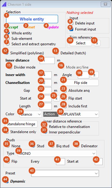
Default state: Whole entity, Format input, Simplified, Inner perpendicular, Stud MONO, Dynamic.
Selection (top left)
| # | Control | What it does |
|---|---|---|
| 1 | Whole entity (button) | Hides the form and picks the reference in the drawing, according to the mode below. The walk starts at the first vertex of the entity. A reference longer than 2000 units is refused. The caption of the button does not change with the mode. |
| 2 | Accept (green) | Keeps the preview as ordinary entities, forgets the reference and the trim reference. Status: Aceito. Selecione nova referência. |
| 3 | Reset (orange) | Erases the preview. |
| 4 | Update (magenta) | Redraws the preview with the current values. |
| 5 | Whole entity | Prompt Select the reference line: the whole line, polyline or arc is the reference. |
| 6 | Sub-element | Prompt Select entity near the segment to use: only the segment of the polyline nearest to your click becomes the reference (arc segments keep their curvature). |
| 7 | Select and extract geometry | Prompt Select the source entity, then First point on the entity and Second point on the entity: the stretch between the two points becomes the reference. |
| status line | Nothing selected in red until a reference is picked; Selection ok in blue afterwards; then the stub count after every redraw. |
Input (top right)
| # | Control | What it does |
|---|---|---|
| 8 | Delete input | Erases the picked entity from the drawing after the pick (Whole entity mode only). |
| 9 | Format input | Also draws the reference redrawn with the Channelisation width (20) on the channelisation layer. On by default. |
Trim reference
| # | Control | What it does |
|---|---|---|
| 10 | Select | Prompt Select the trim reference. An open curve cuts every stub at its first crossing with it (stubs that do not cross it are kept whole). A closed curve keeps only the parts of the stubs inside it. After a trim, every element that had no width receives the Inner width and everything, channelisation included, goes to the strip layer. Status Trim não lido if nothing valid was picked. |
| 11 | x | Forgets the trim reference and redraws. |
Parameters (middle)
| # | Control | What it does |
|---|---|---|
| 12 | Simplified (polylines) | Each stub is one polyline with constant width (default). |
| 13 | Detailed (hatch) | Each stub is a closed parallelogram outline filled with a solid hatch when drawn. |
| 14 | Inner distance (m) | Spacing between stubs, measured perpendicular to the stubs (see 32 and 33). The Inner width is added to the spacing along the reference: with the defaults (1.1 perpendicular, 0.4 wide) the stubs are 1.1 × √2 + 0.4 = 1.96 apart along the line. |
| 15 | Divider mode | Box 14 becomes a number of divisions: the reference is split into that many equal pieces and one stub is placed at every division, with the value taken as is (no width added). Without Include first the stub at the end of the line is dropped. |
| 16 | Mode arc/line | Not available in this version. |
| 17 | Inner width (m) | Width of each stub. A value above 5 is read as centimetres (40 = 0.4 m). |
| 18 | Angle | Angle of the stubs from the reference direction, in degrees. A negative value a is used as −a + 90, so −45 leans the stubs backwards (135°). |
| 19 | ± | Negates the angle and redraws. |
| 20 | Channelisation (m) | Width of the channelisation line drawn by Format input (9) and by Standalone only (34); it also enters the stud offset (see 35). A value above 5 is read as centimetres. |
| 21 | Flip side | Reverses the reference (start and end swap), so the stubs move to the other side of the line and the walk starts from the other end. |
| 22 | Gap (m) | Shortens every stub by this amount, split between its two ends, so the stub also lifts off the reference by half the gap. |
| 23 | Absolute ang | Not available in this version. |
| 24 | Start at (m) | Distance skipped from the start of the reference before the first stub (not used in Divider mode). |
| 25 | x | Resets Start at to 0. |
| 26 | Flip start | Reverses the reference and negates Length (27): the stubs stay on the same side but lean the other way, and the walk starts from the other end. Disabled (and cleared) while Include first is on. |
| 27 | Length (m) | Length of each stub. A negative value draws the stubs on the other side of the line; the studs follow. |
| 28 | Include first | Also places a stub at the start vertex of the reference (in Divider mode, at the end too). |
| 29 | Color | Branco: strips on SINA_HOR_BR_ZPA, channelisation on SINA_HOR_BR_LCA. Amarelo: the SINA_HOR_AM_* pair. |
| 30 | Action | IMPLANTAR draws on the base layers; MANTER, REMOVER and REVITALIZAR add the _MAN, _REM or _REV suffix to every layer. |
Standalone fringe and distance reference
| # | Control | What it does |
|---|---|---|
| 31 | Standalone fringe | With a reference picked: click stations in the drawing (Station for the loose stub (Esc to finish)). At the foot of each click one stub is drawn with the current angle, length and width, permanently (it is not part of the preview) on the channelisation layer. Without a reference the status says Selecione a referência. |
| 32 | Relative to channelisation | Inner distance is used as typed, measured along the reference. |
| 33 | Inner perpendicular | Inner distance is the clear distance perpendicular to the stubs: the value is multiplied by √2 before dividing the line (default). |
| 34 | Standalone only | Draws no stubs at all: only the reference redrawn with the channelisation width, on the channelisation layer. Status Canalização. |
Studs
| # | Control | What it does |
|---|---|---|
| 35 | None | No stud blocks. |
| 36 | Stud | Inserts the TACHA block in the middle of every piece between two stubs, shifted to the stub side by Channelisation/2 + 0.2 (default). Studs go to the strip layer. |
| 37 | Big stud | Inserts TACHAO, shifted by Channelisation/2 + 0.3, on the yellow SINA_HOR_AM_ZPA layer (with the action suffix). |
| 38 | Delineator | Inserts BALIZA at the same stations as Stud. |
| 39 | Type | Visibility state given to the dynamic block: MONO, BI, MONO_PLOTAVEL, BI_PLOTAVEL, GENERICA_VAZADO, GENERICA_PREENCHIDO. SEM draws no studs. |
| 40 | Flip | Rotation of the stud block: without Flip every block is turned 180° from the line direction; with it, 0°. |
| 41 | Every | 1 keeps every stud; a value n above 1 keeps one stud in every n, counted from Start at (42) on (the studs before it are all kept). |
| 42 | Start at | With Every = 1, the first Start at − 1 studs are skipped. |
Preset and Dynamic
| # | Control | What it does |
|---|---|---|
| 43 | Preset | Loads a set of values and redraws. Built-in: the presets of the active country profile, plus ACOSTAMENTO (3.2 / 0.4 / 0.2) and AIRPORT (5, widths 0.4 / 0.4, angle 90, no studs). Values are distance / inner width / channelisation. The Brazilian presets are listed on the Portuguese page. |
| 44 | Dynamic | Live preview on. When it is off nothing is redrawn, not even by Update, until it is on again. |
How the options combine
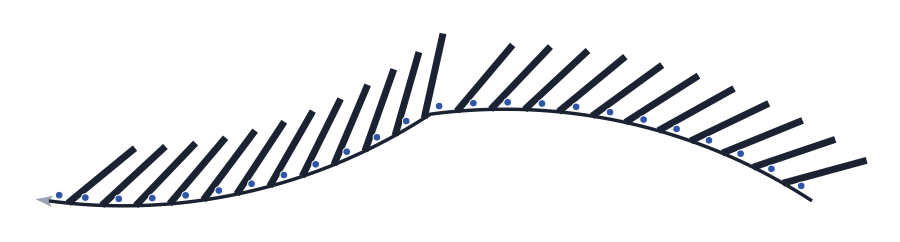
All figures were produced by running the command's own engine on the same sample reference (length 46.09, grey, arrow at the end). Stubs are black, studs are blue dots.
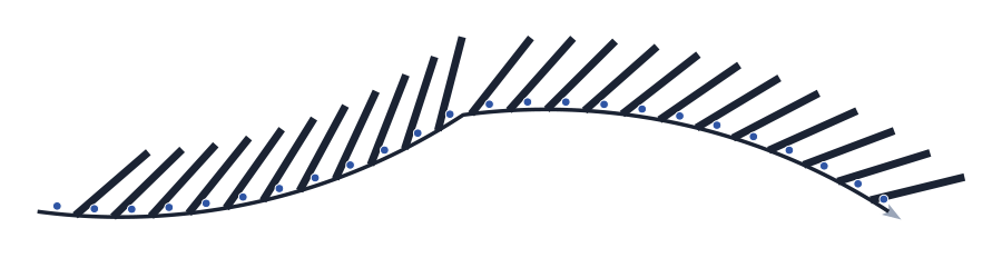
Defaults: Inner distance 1.1 (perpendicular), width 0.4, angle 45°, length 5. The stubs are on the left of the walking direction; the reference is redrawn as the channelisation line (Format input).
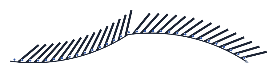
Relative to channelisation: the same 1.1 is used along the line, so the stubs are closer (1.1 + 0.4 = 1.5 apart).
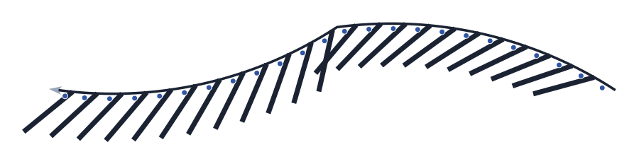
Flip side: the reference is walked from the other end; the stubs change side.
Flip start: the reference is reversed and the length negated, so the stubs keep their side but lean the other way.
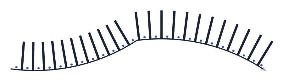
Angle 90: stubs perpendicular to the reference.
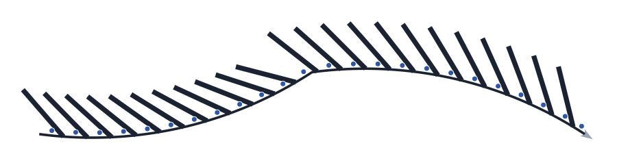
Angle −45: used as −(−45) + 90 = 135°, the stubs lean backwards.
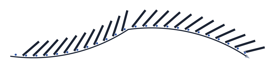
Gap 1: every stub is 1 unit shorter (4 instead of 5) and starts 0.5 away from the line.
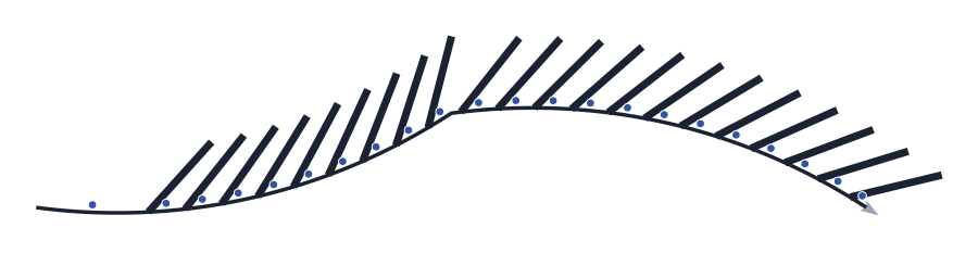
Start at 4: the first stub lands 4 units later.
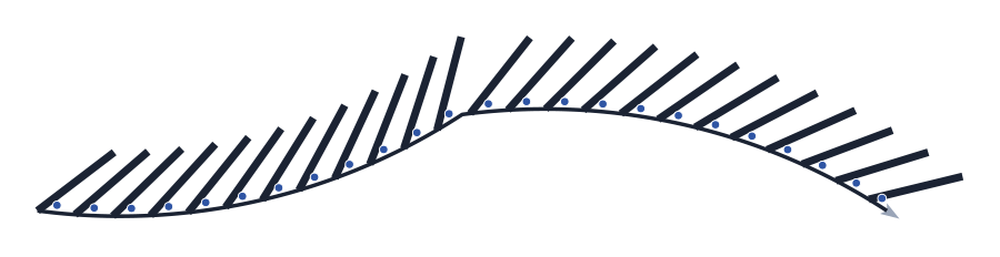
Include first: an extra stub at the start vertex.
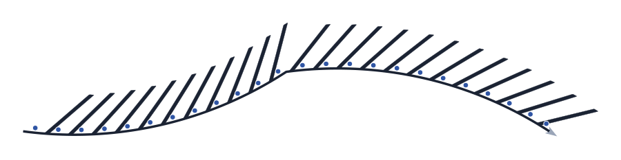
Detailed (hatch): each stub is a closed parallelogram, filled when drawn.
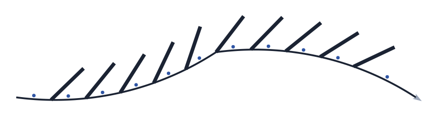
Divider mode with 12: the line is split into 12 equal pieces and one stub is placed at each division (start and end excluded).
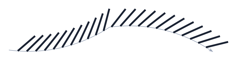
Format input off and studs None: stubs only, the reference is not redrawn.
Remembered between sessions
Nothing. The form opens with its defaults every time (Inner distance 1.1, width 0.4, angle 45, channelisation 0.2, length 5, white, IMPLANTAR, stud MONO). Presets are built in and cannot be saved from this form.
Notes
- The two-flow tool (
marking-area-2-flows) draws the V-shaped chevrons between two converging lines; this tool draws only the stubs off one line. The three-flow tool uses this same tool for its Chevron 1 side methods. - Closing the form keeps the last preview in the drawing (it is not erased).
- Mode arc/line (16) and Absolute ang (23) are not available in this version.
- The status texts are shown as they are written in the program: some of them are in Portuguese in the English form.
- Widths typed above 5 are read as centimetres (40 = 0.40 m), so old values keep working.