| Command | CAPCAD_MARKING_STRIP |
| Shortcut | none (DF runs CAPCAD_MARKING_STRIP_CONTRAN, see Also; DC runs CAPCAD_ROAD_SET) |
| Ribbon | CapCad tab › Traffic Control panel › Markings split button › Longitudinal |
| Category | Horizontal |
| Form | DesenhaConjuntoForm "Draw Set" (modeless: the drawing stays live while it is open) |
| Hosts | AutoCAD |
| Also | CAPCAD_ROAD_SET (DC) opens the same form without pre-selecting the road-marking folder; the Compositor's Test in dwg opens it already loaded with a definition. CAPCAD_MARKING_STRIP_CONTRAN (DF) is the other way to draw a marking: a separate form (RoadStripForm) where you describe one line of the active country profile's norm by colour, cadence and code instead of picking a definition, with the same three ways of choosing the base (alignment stretch, selected entities, two points), a Copy properties pick that reads an existing marking's layer back into the form, and buttons that hand over to the linetype manager, the alignment trim/break tool, the contrast-backing tool and the learning area. Options of that form that are not available in this version are marked on screen. |
Draw a whole longitudinal marking, not one polyline at a time. The CAD's OFFSET and PLINE give you bare geometry on the current layer. The Marking Strip draws every line of a marking from one definition, on the right layers, with the right widths and dash cadences, and lets you redraw it until it is right.
- One definition, all the lines. A double solid centre line, a solid-plus-broken line, a contrast-backed blue lane: each is one entry in the library, and one Apply draws all its lines together.
- Layers that mean something. Each line lands on a
SINA_HOR_…layer whose name states the colour, the dash cadence and the code of the marking. The layer is created for you, coloured for you, and gets a dashed linetype generated from its own name. - Cadence from the name.
4x8in the layer name is a 4 m dash with an 8 m gap. Change the token and the linetype follows: no.linfile to edit. - Parameters, not copies. Widths, spacings and lane widths are variables you edit in a panel; the lines are recomputed from them on every redraw.
- Live redraw. Change a variable, the offset or the direction and click Update or Invert: the previous preview is erased and drawn again.
- Fifteen countries built in. The definitions ship inside CapCad (Brazil, Spain, UK, USA, France, Portugal, Latin America and more) and work offline; add your own as text files or from CapCloud, and mark favourites.
What it does
The Marking Strip opens the Draw Set form with the road-marking folder of the library already selected (ROAD MARKING in an English session, FAIXAS in Portuguese, DEMARCACIONES in Spanish). You pick a definition on the left, choose how the base line will be obtained in the middle, adjust the variables on the right, and click Apply. The command then reads the base from the drawing and draws every line of the definition along it.
A definition is a short text (the dctext). Its lines look like this:
;@description Continuous / broken line (LFO-4)
var largura = 0.10
var distancia = 0.10
f, SINA_HOR_AM_LFO4, -(largura+distancia)/2, largura
f, SINA_HOR_AM_4x8_LFO4, (largura+distancia)/2, largura
var name = valuedeclares a variable. These are the rows of the Variables panel.f, layer, offset, widthdraws one line (a faixa): a copy of the base shifted sideways by offset, on layer, as a polyline of constant width. Offset and width may be expressions over the variables.p, sign, offset, distance, direction, left-edgeinserts a sign at a station (none of the shipped road-marking definitions use it).;starts a comment;;@descriptionand;@previeware read as the description and the preview image.
The layer grammar
Every line's layer name is a sentence: SINA_HOR _ colour _ cadence _ code, with an optional material token (the one containing +) and an optional action suffix (_REM remove, _MAN keep, _REV renew). The command parses the name and derives the layer's colour and linetype from it:
| Token | Meaning | Examples |
|---|---|---|
| colour | two letters: BR white, AM yellow, PR black, VM red, AZ blue, LA orange, VD green |
SINA_HOR_AM_LFO1 is yellow |
| cadence | WxH = dash W units, gap H units; a device letter pair may follow (TA stud/tacha, TO tachão, BA delineator, CO cone, SC supercone); TA4 alone = studs every 4 with no painted line; CTA4 = continuous line plus studs |
4x8 dash 4 gap 8; 2x2TA dash 2 gap 2 with studs; no token = continuous |
| code | the marking's code in its manual | LFO2, LMS1, LBO, D1013.1 |
In an English session the layer is written to the drawing in the English spelling of the same grammar: ROAD_MARK_YE_4x8_LFO2 (BR→WH, AM→YE, PR→BK, VM→RD, AZ→BL, VD→GR, LA→OR, and _REM/_MAN/_REV become _REMOVE/_KEEP/_RENEW). In Spanish it is SENA_HOR_… with BR→BL, VM→RJ, PR→NG, LA→NA. The definitions themselves always use the SINA_HOR spelling; the translation happens when the layer is created.
Colours come from the layer-domain rules: white 255, yellow 40, black 250, red 1, blue 5, orange 30, green 3; a yellow line with _REM is 6, with _MAN 253, with _REV 4; a white line with _REM is 10, _MAN 253, _REV 3. If a rule matches nothing the layer is created with colour 7.
Cadence linetypes
When the cadence token is a plain WxH, the command creates (once per drawing) a linetype named exactly like the token, 4x8, with a 4-unit dash and an 8-unit gap, and assigns it to the layer. The units are drawing units, with no scaling. Tokens that carry a device (2x2TA, TA4, CTA4) do not get a generated linetype in this version: the layer is created with the right colour and the line is drawn Continuous.
Workflow
- Run
CAPCAD_MARKING_STRIP. The form opens beside the drawing with the road-marking folder selected in the folder list (5). - Click a definition in the list (7). Its name (8), description (9), variables (34) and preview picture appear.
- Edit the variables (34) if needed, for example
largura(width) orlarguraTotal(carriageway width). - Choose how the base line is obtained on the Longitudinal tab (12, 15 or 17), or use the Transversal tab (18) to define the base from two edge points.
- Set an Offset (24) if the whole marking should sit beside the base rather than on it.
- Click Apply (select base) (33). The form hides, the CAD prompts for the base, and the lines are drawn. The status line reports how many lines were drawn.
- Not right? Change a variable or the offset and click Update (31); click Invert (32) if the lines landed on the wrong side; Reset (29) erases the preview; Zoom (30) frames the base.
- Click Apply again for the next base. The previous lines stay in the drawing.
The form
Numbers are the same in every screenshot of this page. The Transversal tab (18 to 22) and the dctext box (36) keep their numbers where they show.
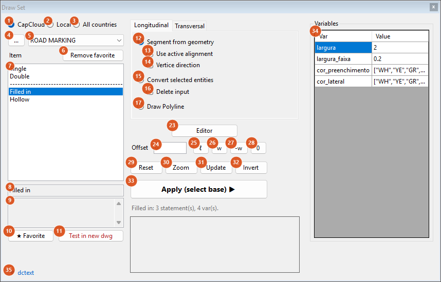
As the command opens it in an English session: source CapCloud, folder ROAD MARKING, with "Filled in" selected so the Variables panel is populated. The list shows the entries of the active country profile.
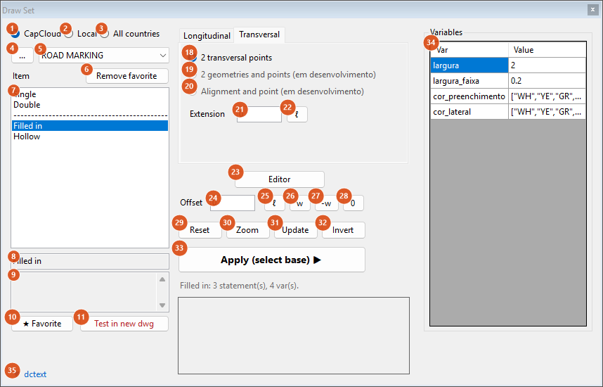
The Transversal tab: only "2 transversal points" (18) is live; 19 and 20 are disabled.
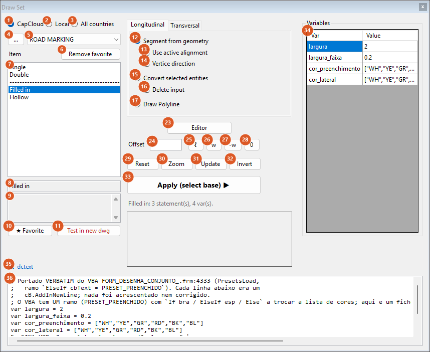
Clicking "dctext" (35) grows the form and shows the definition text (36), which you can edit in place.
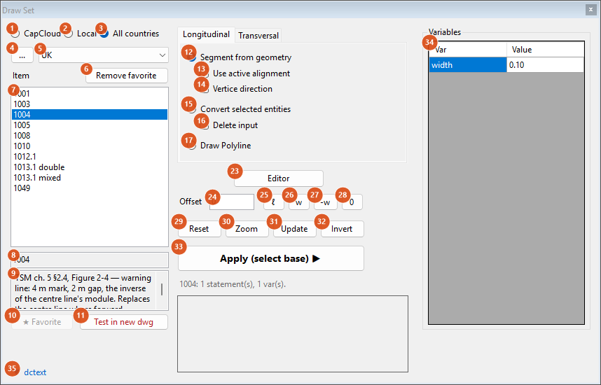
"All countries" (3) lists the library embedded in CapCad, one folder per country; here UK › 1004 with its description and variable.
Library (left column)
| # | Control | What it does |
|---|---|---|
| 1 | CapCloud | Folders come from the CapCloud server plus the fixed categories OBSTÁCULOS, ROAD MARKING (the folder this command pre-selects), AIRPORT, INDUSTRIAL and *FAVORITES*. A Brazil or airport profile, or a Spanish session, sees the whole list; any other profile sees only UK and ROAD MARKING. If the server cannot be reached the status line says so and the built-in entries are still listed. |
| 2 | Local | Folders are the sub-folders of your local library root (the project's DesenhaConjunto folder when the project has one, else the library's DesenhaConjunto\ or LinearSet\ folder); .. is the root itself. Items are the .txt files inside. |
| 3 | All countries | Folders are the ones embedded in CapCad, regardless of profile: ARGENTINA, BRASIL, CANADA, CHILE, COLOMBIA, COMMON, ECUADOR, ESPANHA, FRANCE, MEXICO, PARAGUAI, PERU, PORTUGAL, SIECA, UK, USA (171 definitions). Favorite (10) is disabled in this mode. |
| 4 | … | Pick a local library folder; switches the source to Local. Applies to this form only, it does not change the project. |
| 5 | Folder | The folder list. Selecting one lists its items (7): in CapCloud mode the fixed names for that folder come first, then the server listing. |
| 6 | Remove favorite | Removes the selected item from your favourites. Only works while the *FAVORITES* folder is open ("Open *FAVORITES* to remove." otherwise). |
| 7 | Item list | Selecting a definition loads it. Loading fills 8, 9, 34, the preview picture, and the status line (name: N statement(s), M var(s).). A name that nothing answers to loads an empty definition ("Empty definition."). |
| 8 | Name (read-only) | The selected definition's name. |
| 9 | Description (read-only) | The ;@description line of the definition. |
| 10 | ★ Favorite | Saves the selected item as folder\name (\folder\name for local ones) under the *FAVORITES* folder. "Select an item first." when nothing is selected. |
| 11 | Test in new dwg (red) | Asks New dwg will be open and this definition draw in it. Proceed?; on Yes opens a new drawing, draws a 100-unit straight line from (0,0) on a layer named curve (colour 8), draws the definition on it and zooms to it. Needs a definition ("Pick a definition first."). |
| preview | The picture box under the Apply button shows the definition's ;@preview image, or the shared figure for its name (single/double solid, dashed, solid-plus-dashed, in yellow or white). Click it to open the file in your image viewer. Blank when there is no picture. |
Longitudinal tab (how the base is obtained)
| # | Control | What it does |
|---|---|---|
| 12 | Segment from geometry | On Apply: Select the reference curve: (any curve; "Must be a curve." otherwise), then Point 1: and Point 2:. The base is the stretch of the curve between the two points. Unless 14 is ticked, the base is turned so it starts at the end nearest Point 1, so the walking direction (and the side offsets land on) follows your picks. "Could not determine the segment." when the points do not define a stretch. |
| 13 | Use active alignment | Skip the curve pick: the project's alignment (eixo) is the reference and only the two points are asked. If no project alignment is found, the CAD says Project alignment not found — select the curve. and asks for the curve as usual. |
| 14 | Vertice direction | Keep the curve's own vertex order as the walking direction instead of orienting towards Point 1. |
| 15 | Convert selected entities | On Apply: select entities (polylines, lines, arcs, splines are accepted). Each one becomes a base, whole, in its own vertex order, and the definition is drawn on every one. |
| 16 | Delete input | With 15: after drawing, the selected source entities are erased. |
| 17 | Draw Polyline | On Apply: First point:, then Next point (Enter to finish): repeatedly. The clicked points form the base. The base itself is not added to the drawing, only the marking. |
Transversal tab
| # | Control | What it does |
|---|---|---|
| 18 | 2 transversal points | On Apply: pick point 1 on the LEFT edge and point 2 on the RIGHT edge of the carriageway (the prompts are in Portuguese: Ponto 1, bordo ESQUERDO, Ponto 2, bordo DIREITO). The distance between them is written into the variable larguraTotal (34), added if the definition does not have it. The base becomes a short line through the midpoint of the two points, perpendicular to them, 0.01 units to one side and Extension (21) to the other, and the definition is drawn along it. This is how an edge line such as LBO (larguraTotal/2 - afastamentoBordo) is placed from the real carriageway width. |
| 19 | 2 geometries and points | Not available in this version. |
| 20 | Alignment and point | Not available in this version. |
| 21 | Extension | Length of the transversal base line. 0 means 20 units. |
| 22 | ℓ | Measure the extension in the drawing (prompt Extensão longitudinal:). |
Definition and offset (middle)
| # | Control | What it does |
|---|---|---|
| 23 | Editor | Opens the Linear Set — Line Definition dialog (modal) with the current dctext: a read-only grid of the parsed statements (Type, Layer, Offset, Width), an info line (N statement(s) • linear/pontual • M var(s) • description), the text itself, Add statement (appends f, LAYER, 0, 0.10), Draw on alignment ▶ (accepts the text back into the form as definition "(editor)"), Load… and Save… (.dc or .txt files). Cancelling leaves the form's definition unchanged. |
| 24 | Offset | Shifts the whole base sideways before the definition is drawn. Positive moves it to the left of the walking direction, negative to the right (see the figure). Comma or dot accepted; empty = 0. |
| 25 | ℓ | Measure the offset in the drawing (prompt Offset distance:). |
| 26 | w | Set the offset to the definition's width variable: the first of w, width, largura that exists. "No w/width/largura variable in the definition." otherwise. |
| 27 | -w | The same, negated. |
| 28 | 0 | Set the offset to 0. |
| 29 | Reset | Erase the current preview lines ("Preview erased."). Signs inserted by p statements are not erased. |
| 30 | Zoom | Frame the base line(s) with 40 % margin. |
| 31 | Update | Erase the preview and draw it again with the current dctext, variables and offset. "Apply first." when there is no base yet. |
| 32 | Invert | Reverse the walking direction of every base and redraw: every offset changes side. "Apply first." when there is no base yet. |
| 33 | Apply (select base) ▶ | Start a new preview: hide the form, obtain the base(s) as chosen on the tabs, draw the definition on each, show the form again. The previous preview is kept as ordinary entities. "Pick a definition first." with an empty definition; "No base geometry." when the pick produced nothing. |
| status line | Grey text under Apply. After a draw: N line(s) on M base(s), followed by , P placa(s) (not erased by Reset) when signs were inserted, , K statement(s) skipped when some lines could not be drawn, and the reasons in brackets (see Messages). |
Variables (right) and dctext (bottom)
| # | Control | What it does |
|---|---|---|
| 34 | Variables | One row per var line of the definition: name (read-only) and value (editable). The values are substituted into the definition before every Apply, Update, Invert or test draw. Cells left empty keep the definition's own value. |
| 35 | ▼ dctext | Grows the form to show the definition text (36); click again to hide it. |
| 36 | dctext box | The definition text itself. Every keystroke re-parses it: the Variables panel and the preview picture refresh, and the status line reads N statement(s), M var(s) — edited., or dctext: |
How the options combine
All figures below were produced by running the command's own engine (definition parser, variable substitution, offset rules and layer grammar) on a sample base line of 30.9 units, drawn dashed with an arrow at its end; the marking lines are drawn in the colour and dash pattern the layer name gives them. No CAD was involved, so the pictures show geometry only.
One definition, one or more lines

LFO-1: f, SINA_HOR_AM_LFO1, 0, largura: one yellow continuous line, width 0.10, centred on the base (offset 0).

LFO-2: f, SINA_HOR_AM_4x8_LFO2, 0, largura: the same line on a layer whose cadence token is 4x8, so the layer gets the generated linetype 4x8 (dash 4, gap 8).

LFO-3: two statements at -(largura+distancia)/2 and +(largura+distancia)/2: a double continuous line, one on each side of the base.

LFO-4: the same two offsets, but the second statement's layer carries 4x8: continuous on one side, broken on the other.

LMS-2: SINA_HOR_BR_4x8_LMS2: the colour token BR makes the lane line white.

UK diagram 1013.1 mixed (folder UK): SINA_HOR_BR_4x2_D1013.1 at -offset/2 and SINA_HOR_BR_D1013.1 at +offset/2: the TSM warning cadence (4 m mark, 2 m gap) beside a continuous line.
The cadence lives in the layer name

LFO-2 with the layer token edited from 4x8 to 2x4 in the dctext box: the norm's row for v < 60 km/h (2 m dash, 4 m gap). Nothing else changes.
Variables

LFO-3 with largura and distancia set to 0.15 in the Variables panel: wider lines, further apart. Compare with the LFO-3 figure above.
Statement offset: sign and edge
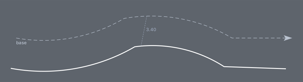
LBO: f, SINA_HOR_BR_LBO, larguraTotal/2-afastamentoBordo, largura with larguraTotal 7 and afastamentoBordo 0.1: the edge line lands 3.40 from the base, on the right of the walking direction (a positive statement offset goes right). The value is measured to the near edge of the stripe: the offset is widened by half the width, so the line's centre is at 3.45.
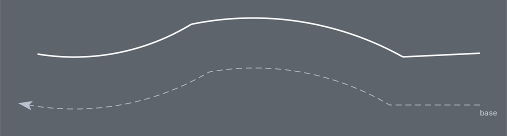
The same after Invert: the base is walked the other way, and the edge line moves to the other side.
The form's Offset box
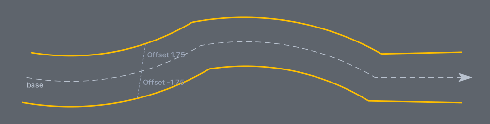
LFO-1 drawn twice with Offset 1.75 and Offset −1.75: the base itself is moved (thin dotted lines) before the definition is drawn on it. Note that the form's positive offset goes to the left of the walking direction, the opposite of a positive offset inside a statement.
Stacked lines

"Faixa azul folga 0.05": a black contrast backing 0.40 wide on SINA_HOR_PR_2.1x1.9, a white line 0.15 wide on SINA_HOR_BR_2x2 and a blue line 0.15 wide on SINA_HOR_AZ_2x2TA. The two thin lines use tiny offsets (±0.00001) so they sit either side of the base; the TA token asks for studs, which are not drawn in this version, so in the CAD that layer is Continuous (the figure shows its 2x2 cadence).
Remembered between sessions
Only the favourites: the *FAVORITES* entries are stored in your user preferences. The form itself is kept alive while the CAD session lasts, so the source, folder, offset and variables you last used are still there when you run the command again in the same session; they are not written to disk. The local library root defaults to the project's DesenhaConjunto folder each time the form is created.
Notes
- Bases from Segment from geometry are trimmed to the stretch between your two points; Convert selected entities uses each entity whole.
- Each
fline becomes one polyline with constant width on its layer; existing layers are re-coloured and re-linetyped to match the name when the marking is drawn. - A statement with offset
0draws on the base itself; a non-zero statement offset is measured to the near edge of the stripe (half the width is added). The form's Offset (24) moves the base before that, with the opposite sign convention: positive left, negative right. - Definitions written with
Tlines (transverse elements such as LRE, LDP and UK 1001) and definitions that build layer names from lists (var cor = ["WH","YE",…]with&, such as Filled in, Hollow and Bordes) are not available in this version: theTlines are skipped, and the list variables stay as written. - Signs inserted by
plines are not part of the preview: Reset and Update leave them in place. - The captions of Transversal options 19 and 20 and some prompts are shown in Portuguese in every language.