| Command | CAPCAD_3D_ASSISTANT |
| Shortcut | none |
| Ribbon | CapCad tab › BIM panel › 3D split button › first button, 3D |
| Category | NEW |
| Form | Form3D "3D Exporter", eleven tabs, modeless |
| Hosts | AutoCAD, BricsCAD, GstarCAD, ZWCAD and ARES Commander |
| Also opened by | the Airport form (CAPCAD_AERO, 3D button on the markings tab), Manage vertical signing (3D button) and Insert Vertical (◰ button) |
Your 2D project already holds everything the 3D model needs: the assistant reads the drawing as it stands and raises the geometry.
- One input scope, several conversions. You select once and tick which families to convert; markings, restraint and blocks are processed in the same pass, against the same elevation reference.
- The elevation comes from the terrain. A Civil 3D surface or a LandXML file gives the Z point by point; with no surface, a fixed elevation serves as the reference and the assistant reports which points fell outside.
- Blocks become their 3D twins. Every pavement block with a library twin whose name ends in
-3Dis swapped automatically, at the same rotation and on the same layer. - The restraint becomes a real solid — posts as boxes, a body swept along the draped path, and retroreflectors placed more densely through curves.
- Undo without surprises. The assistant remembers everything the last run drew and erases exactly that, in one click.
- Samples one click away, to try the workflow before applying it to your own drawing.
What it does
The command opens the 3D Exporter. The Main tab holds the whole decision:
- Which items to convert — lines, legends, restraint, vertical, blocks or stations.
- What the input is — a selection on screen, or everything in model space.
- Where the output goes — the same dwg, a new one, or another open dwg.
- Where the Z comes from — a fixed elevation or a surface.
The Run button validates those four choices, hides the window, asks for the selection (when that applies), walks the input once and runs the ticked conversions. At the end it writes a summary per family to the command line — how many blocks were converted, how many had no 3D twin, how many restraint bodies, supports and retroreflectors, how many solids, devices and marking areas — and, with Report ticked, shows that same text in a window.
The other ten tabs are each family's parameters and utilities.
What the Run button converts
The Run button processes:
| Item | State |
|---|---|
| Lines | Converted. Markings, studs and horizontal-signage areas become thin solids, regions and 3D blocks |
| Restraint | Converted. Guardrails and barriers become posts, a swept body and retroreflectors |
| Blocks | Converted. Pavement blocks with a -3D twin are swapped |
| Legends | Not available in this version. The run skips it and processes the other ticked items |
| Vertical | Not available in this version. |
| Stations | Not available in this version. |
Outside the Run button, the buttons that are not available in this version say so when clicked. They are marked in each tab's table.
Likewise, several options on the parameter tabs are saved with the form but not used by this version. They are identified one by one.
Lines
The line conversion walks the input, keeps only the curves on a horizontal-marking layer of the layer catalogue, and produces:
- Swept solids for the markings that have a width, following the surface at the chosen step;
- Device blocks — stud, large stud, cone — inserted at terrain elevation, looked up first in the local library and then on the server;
- Regions or thin solids for the closed areas, relayered onto the 3D layer matching the source colour.
The layer test accepts a horizontal-marking layer in any of the three spellings the catalogue uses, whatever the active country profile is: the canonical SINA_HOR…, the English ROAD_MARK… and the Spanish SENA_HOR…, each tolerant of a prefix. So a drawing that came in with another profile's layer names is still converted.
With As blocks ticked on the Main tab, the result is grouped into capcad_3d_<id> definitions instead of sitting loose in model space.
Restraint
Every polyline on a guardrail or barrier layer becomes a conversion plan: the posts, the retroreflectors, the path of the body draped over the terrain, and the cross-section profile to sweep, chosen from the type detected in the layer name.
The posts are 0.05 × 0.025 m in section, rise 0.7 m above the terrain and go 1.15 m below it; the body goes onto the layer the plan suggests (CAPCAD_3D_DEFENSA or CAPCAD_3D_BARREIRA) or, with Keep the original layer colour ticked, onto the source polyline's layer. The posts and the retroreflectors use CAPCAD_3D_DEFENSA_SUPORTE and CAPCAD_3D_EPS_CATADIOPTRICO.
A polyline whose layer contains neither "DEFENSA" nor "BARREIRA" is ignored, even when it is in the selection — that is the filter that stops a mixed selection from sweeping the whole drawing. The two words are matched literally, in Portuguese, whatever the language of the session.
Blocks
Every block reference in the input is tested: an empty name, a name already ending in -3D/$3D, or a block outside the pavement catalogue makes the assistant skip it. For the rest, it normalises the name, looks in the library for the definition <name>-3D and, failing that, <name>$3D. Found, it inserts at the same XY position, at the same rotation and on the same layer, with the Z of the elevation reference — plus the visual compensation when the Z came from a surface. Not found, the block goes into the "no 3D twin" count.
Workflow
- Run
CAPCAD_3D_ASSISTANT. - Choose the elevation reference: 3D with default elevation (6) and the value in 7, or Surface (8) and a surface from the list (47). For a terrain in a file, use Load landXML… (9).
- Tick the item to convert (11, 14, 17, 22, 27 or 30) and its sub-options.
- Choose the input — On screen (4) or All (2) — and whether the input should be erased afterwards (5).
- Choose the output (35 to 37).
- Adjust the family's parameters on the matching tabs.
- Click Run (1). With On screen, select the objects.
- Check the summary. If something came out wrong, Delete last drawn (46) erases exactly what the run created.
The form
The numbers below apply across the whole page, all eleven tabs included.
About the captures. The screenshots are of a Portuguese session, because they are the numbered figures shared with the Portuguese edition. The layout and the control numbers are identical in English, and the tables below quote every control as the English build shows it. A handful of captions have no English text and stay Portuguese in every language; they are listed in the Notes and quoted here as they appear.
Tab 1: Main
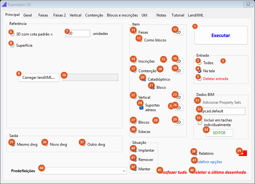
The Main tab. The two elevation-reference options show unticked here because it is the command that fills the surface list when it opens: in the CAD, with neither a surface nor a LandXML, "3D with default elevation" is ticked and "Surface" disabled.
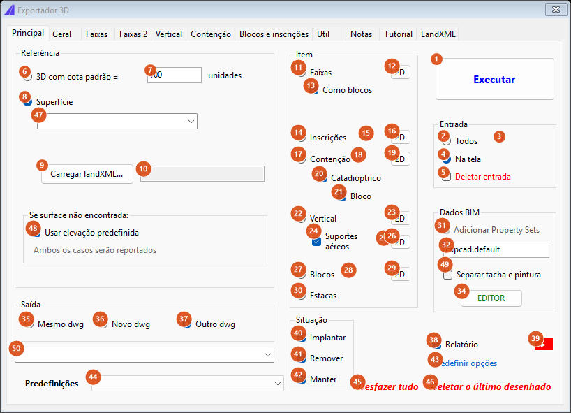
Choosing Surface reveals the surface list (47) and the "If the surface is not found" frame (48); choosing Another dwg reveals the list of open drawings (50). Ticking "As blocks" (13) swaps box 33 for box 49.
Run, input and output
| # | Control | What it does |
|---|---|---|
| 1 | Run | Validates the four choices, hides the window and runs the conversion. Each failing validation highlights its frame in light blue and explains what is missing. |
| 2 | All | The input is the whole of model space. After a run, the form returns to On screen by itself. |
| 3 | ? | Opens the reminder: entities on frozen or off layers will not be included. |
| 4 | On screen | The input is a selection you make after clicking Run. It is the default, and it is where the form returns after every run. |
| 5 | Delete input | Erases the converted 2D geometry. Disabled with New dwg (36) — a new drawing has nothing to erase. |
| 35 | Same dwg | The 3D geometry is created in the current drawing. |
| 36 | New dwg | A new drawing. Not available in this version: the assistant converts in the current dwg. |
| 37 | Another dwg | One of the open drawings, chosen in 50. Not available in this version: the assistant converts in the current dwg. |
| 50 | (target dwg) | The list of open drawings. Only shown with 37. The validation requires the chosen name to be on the list. |
| 38 | Report | Shows the run summary in a text window, as well as writing it to the command line. |
| 39 | ▶ | Opens the tutorial video in the browser. |
| 43 | Reset options | Returns only the four decision frames — reference, output, items and input — to their defaults, and forces Use the default elevation back on. The other tabs' parameters are untouched. |
| 44 | Presets | Three items. Surface Civil 3D para Infraworks and Configuração recomendada require a loaded surface — without one they say so and apply nothing; with one they tick Surface + On screen + Same dwg (highlighting all three) and set a linear step of 4 for lines and restraint. Outro dwg only selects output 37. After applying, the combo clears itself. |
| 45 | Undo all | After confirmation, runs the CAD's UNDO Back, which rewinds to the last mark. This is not the same as 46: it can undo more than the conversion. |
| 46 | Delete last drawn | Erases the entities created by the last run, after confirming and saying how many there are. With no run in this session, it says so. |
Elevation reference
| # | Control | What it does |
|---|---|---|
| 6 | 3D with default elevation = | The Z of everything is the value in 7. |
| 7 | (elevation) | The fixed elevation, in drawing units. |
| 8 | Surface | The Z comes from the surface chosen in 47 or from the LandXML loaded in 9. Disabled when there is neither a Civil 3D surface nor a LandXML. |
| 9 | Load landXML… | Opens a file picker, tries to read the surface and — succeeding — records the folder, fills 10 and reports the number of triangles and points. Failing, it says so. |
| 10 | (LandXML path) | The loaded file. |
| 47 | (surface) | The Civil 3D surfaces. With more than one, the item <all> is added and selected. Only shown with 8. |
| 48 | Use the default elevation | Where the surface does not answer, use the elevation from 7 instead of discarding the point. Only shown with 8. |
With Follow the triangulation ticked on Lines (55) or Restraint (98), the validation refuses the <all> surface: choose a single one.
If the chosen elevation is zero, the output is the same dwg and Delete input is unticked, the assistant asks before running — the 3D would sit stacked exactly on the 2D.
Items
| # | Control | What it does |
|---|---|---|
| 11 | Lines | Converts the horizontal signage. |
| 12 | 2D | Opens CAPCAD_MARKING_STRIP_CONTRAN, the matching 2D command. |
| 13 | As blocks | Groups the line result into capcad_3d_<id> block definitions. Clicking the control already selects the Lines item. Ticking it hides 33 and shows 49. |
| 14 | Legends | Selects the pavement legends. Not available in this version: the run skips it and carries on with the other items. |
| 15 | ? | Opens the reminder: hatches included. |
| 16 | 2D | Opens CAPCAD_MARKING_INSCRIPTION. |
| 17 | Restraint | Converts guardrails and barriers. |
| 18 | ? | Opens the reminder: guardrails and barriers included. |
| 19 | 2D | Opens CAPCAD_RESTRAINT, the Road Restraint command. |
| 20 | Retroreflective | Inserts the retroreflectors on the posts. |
| 21 | Block | Uses the block chosen in 104 as the retroreflector instead of the solid. Saved with the form; not used by this version. |
| 22 | Vertical | Selects the signs. Not available in this version. |
| 23 | 2D | Opens CAPCAD_SIGN_INSERT, Insert Vertical. |
| 24 | Overhead supports | Makes the block pass run alongside the Vertical item, restricted to overhead-support blocks — names containing PORTICO, BRACO or SEMI. |
| 25 | ? | Opens the reminder: overhead supports included (cantilever and gantry). |
| 26 | 2D | Opens CAPCAD_DEVICE_INSERT, the road device library. |
| 27 | Blocks | Converts 2D blocks into their 3D twins. |
| 28 | ? | Opens the reminder: blocks are converted when a twin block with the suffix -3D or $3D exists. |
| 29 | 2D | Opens CAPCAD_DEVICE_INSERT. |
| 30 | Stations | Not available in this version. |
| 40 | Insert | Saved with the form; not used by this version. |
| 41 | Remove | Likewise. |
| 42 | Keep | Likewise. |
The block pass also runs automatically when Restraint is ticked — restricted then to restraint accessory blocks, whose names contain DEFENSA, BARREIRA, TERMINAL, ABSORVEDOR or CATADIOPTRICO.
BIM Data
| # | Control | What it does |
|---|---|---|
| 31 | Add Property Sets | Only enabled on Civil 3D. Saved with the form; not used by this version. |
| 32 | (style) | The name or path of the project's cloud style, filled in by the command. |
| 33 | Include on studs individually | Only visible while As blocks (13) is unticked. Saved with the form; not used by this version. |
| 49 | Separate stud and paint | Takes the place of 33 when As blocks is ticked: it separates the stud groups from the paint groups. It is used by the line conversion. |
| 34 | EDITOR | Opens CAPCAD_PSET_EDIT, the Property Sets editor. |
Tab 2: General
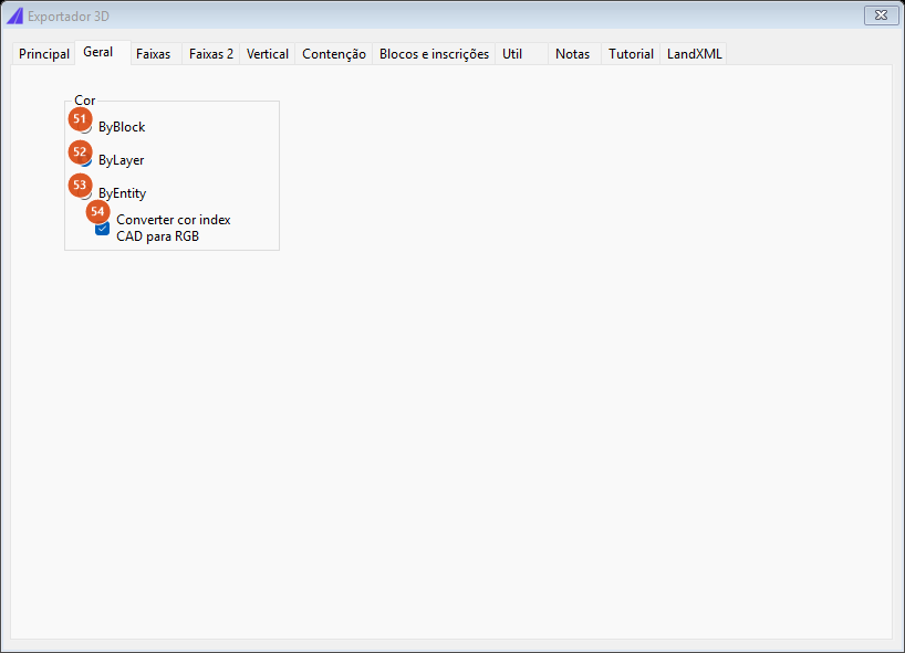
| # | Control | What it does |
|---|---|---|
| 51 | ByBlock | The colour of the horizontal 3D geometry is ByBlock. It is the only one of the three the run reads. |
| 52 | ByLayer | Default. With it (or 53), the geometry is not forced to ByBlock. |
| 53 | ByEntity | No distinct effect in this version. |
| 54 | Convert CAD index colour to RGB | Saved with the form; not used by this version. |
Tab 3: Lines
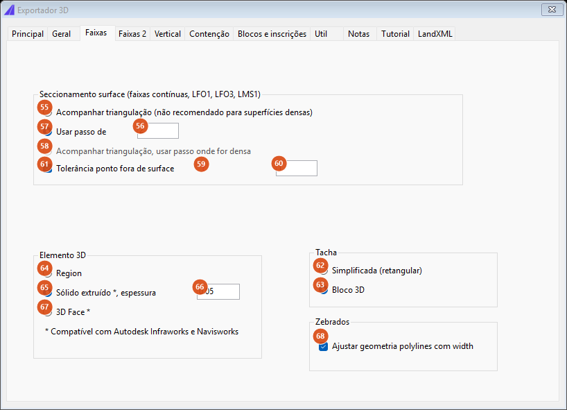
| # | Control | What it does |
|---|---|---|
| 55 | Follow the triangulation (not recommended for dense surfaces) | Samples the marking at the surface's triangulation vertices. Not used by this version's run, but it does take part in the validation: with it ticked, the <all> surface is refused. |
| 56 | (step) | The step, in drawing units. Default 2. |
| 57 | Use a step of | Samples the marking every 56 units. It is the default, and it is the mode the run uses. Unticked, the marking follows its own vertices. |
| 58 | Follow the triangulation, use the step where it is dense | Not available in this version. |
| 59 | ? | Opens the reminder: tolerance for marking points falling off the surface. |
| 60 | (tolerance) | The value. |
| 61 | Tolerance for a point off the surface | Saved with the form; not used by this version. |
| 62 | Simplified (rectangular) | Studs come out as rectangles. |
| 63 | 3D block | Studs come out as 3D blocks from the library. It is the default, and it is the box the run reads. |
| 64 | Region | Closed areas come out as regions. |
| 65 | Extruded solid *, thickness | Closed areas come out as thin solids. It is the default. The asterisk points to the note "* Compatible with Autodesk Infraworks and Navisworks". |
| 66 | (thickness) | The solid's thickness. Saved with the form; not used by this version: the solids come out with a fixed thin thickness. |
| 67 | **3D Face *** | Saved with the form; not used by this version. |
| 68 | Adjust the geometry of polylines with width | Saved with the form; not used by this version. |
Tab 4: Lines 2
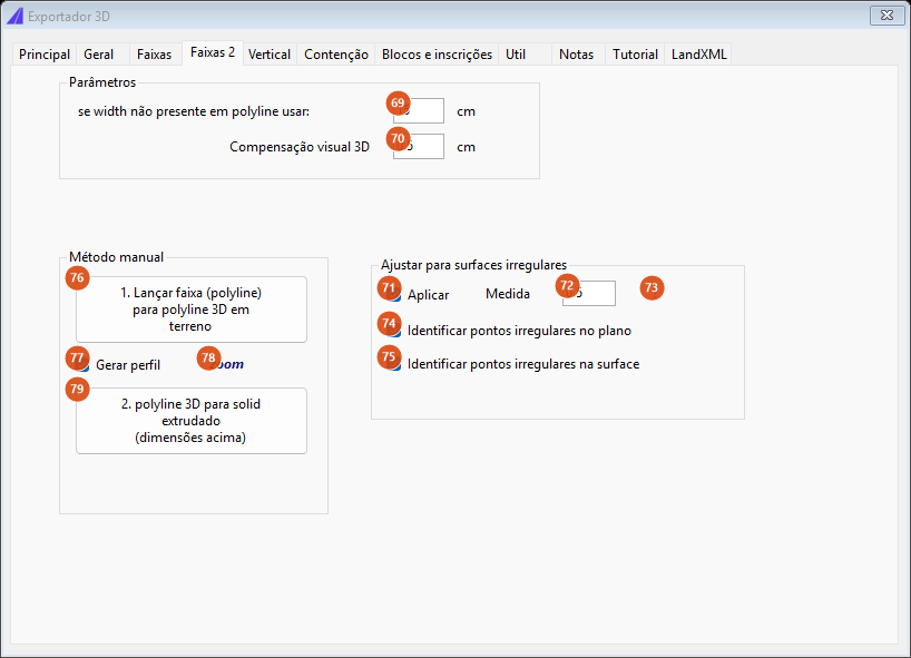
| # | Control | What it does |
|---|---|---|
| 69 | if the polyline has no width use: | The width, in centimetres, applied to polylines without one. Default 15. Read by the run. |
| 70 | 3D visual compensation | How far the 3D geometry rises above the terrain, in centimetres, so that it does not sink into the surface. Default 0.5. Read by the run. |
| 71 | Apply (irregular-point adjustment) | Saved with the form; not used by this version. |
| 72 | Measure | Likewise. |
| 73 | ? | Opens the reminder: adjustment of abrupt points on irregular surfaces. |
| 74 | Identify irregular points on the plane | Saved with the form; not used by this version. |
| 75 | Identify irregular points on the surface | Likewise. |
| 76 | 1. Project the line (polyline) onto a 3D polyline on the terrain | Not available in this version. |
| 77 | Generate profile | Saved with the form; not used by this version. |
| 78 | zoom | Not available in this version. |
| 79 | 2. 3D polyline to extruded solid (dimensions above) | Not available in this version. |
Tab 5: Vertical
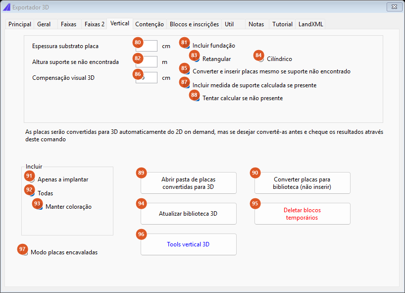
The sign conversion is not available in this version; the fields are saved with the form.
| # | Control | What it is for |
|---|---|---|
| 80 | Sign substrate thickness | The plate thickness, in centimetres. |
| 81 | Include the foundation | Draws the support's foundation. Enables 83 and 84. |
| 82 | Support height when not found | Default height, in metres. |
| 83 | Rectangular | Rectangular foundation. |
| 84 | Cylindrical | Cylindrical foundation. |
| 85 | Convert and insert signs even when the support is not found | Does not stop the conversion for want of a support. |
| 86 | 3D visual compensation | In centimetres. |
| 87 | Include the calculated support measure when present | Uses the support height recorded on the sign. Enables 88. |
| 88 | Try to calculate it when absent | Works the height out when it is not recorded. |
| 89 | Open the folder of signs converted to 3D | Opens the project's proposed-signs folder in Explorer. With no valid folder, it says so. |
| 90 | Convert signs into the library (do not insert) | Not available in this version. |
| 91 | Only those to insert | Restricts to the signs to be installed. |
| 92 | All | Default. |
| 93 | Keep the colouring | Preserves the sign's colours. |
| 94 | Update the 3D library | Not available in this version. |
| 95 | Delete temporary blocks | Not available in this version. |
| 96 | Tools vertical 3D | Runs CAPCAD_3D_SIGN_CHECK, which opens the sign-drawing validation on its 3D page — see Fix Traffic Signs. |
| 97 | Overlapping signs mode | Mode for signs that overlap one another. |
The tab also carries the form's own note: signs are converted to 3D from the 2D automatically, on demand; this command is for converting them beforehand and checking the result.
Tab 6: Restraint
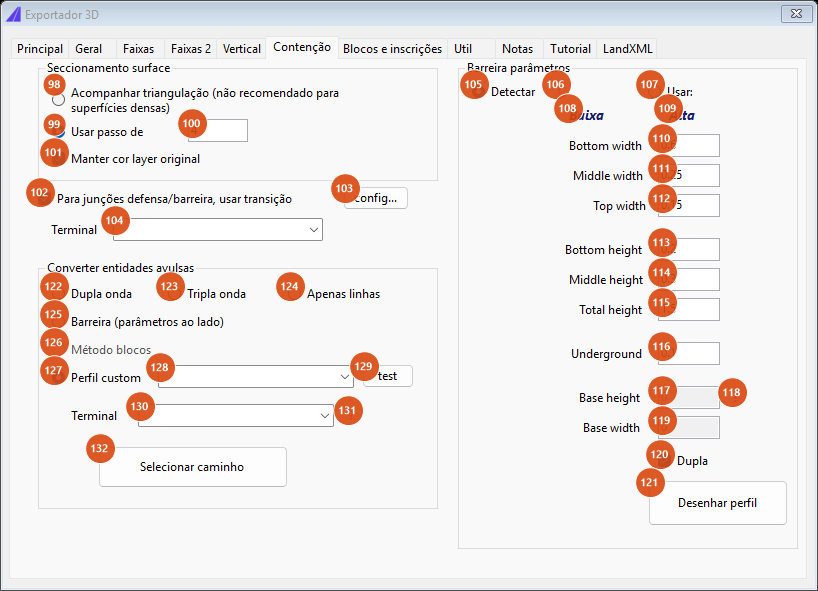
| # | Control | What it does |
|---|---|---|
| 98 | Follow the triangulation (not recommended for dense surfaces) | Not used by this version's run, but it does take part in the <all> surface validation. |
| 99 | Use a step of | Samples the path every N units, N being in 100. It is the default and it is what the run uses; unticked, the path follows its own vertices (arcs flatten). |
| 100 | (step) | The step. Default 4. |
| 101 | Keep the original layer colour | The body and the posts stay on the source polyline's layer instead of the suggested 3D layer. Read by the run. |
| 102 | For guardrail/barrier joins, use a transition | Saved with the form; not used by this version. |
| 103 | config… | Not available in this version. |
| 104 | Terminal (retroreflector) | The retroreflector block, loaded from the project library's DEFENSA-catadioptrico folder, with Catadioptrico-3D pre-selected when it exists. Saved with the form; not used by this version, which draws the retroreflector as a solid. |
| 105 | Detect (barrier) | The barrier's dimensions come from the layer name. Default. |
| 106 | ? | Opens the reminder: the barrier's parameters are detected from the layer name. |
| 107 | Use: | Uses the values typed into 110 to 120. |
| 108 | Baixa (low) | Fills in the low profile: heights 0.175 / 0.25 / 0.9. |
| 109 | Alta (high) | Fills in the high profile: heights 0.2 / 0.3 / 1.5. Both links write widths 0.6 / 0.25 / 0.15, underground 0.1, base zeroed, untick Double and tick 107. |
| 110 to 117 and 119 | Bottom width, Middle width, Top width, Bottom height, Middle height, Total height, Underground, Base height and Base width | The barrier's dimensions, in metres, in that order. |
| 118 | ? | Opens the reminder: barrier base — reserved. |
| 120 | Double | A double (symmetrical) profile instead of a half profile. |
| 121 | Draw profile | Not available in this version. |
| 122 | Double wave | Profile for the loose-curve conversion. |
| 123 | Triple wave | Likewise. |
| 124 | Lines only | Likewise. |
| 125 | Barrier (parameters alongside) | Likewise, using the frame on the right. |
| 126 | Blocks method | Not available in this version. |
| 127 | Custom profile | Default; uses the block from 128. |
| 128 | (profile) | ARMCO H4b and any further profile blocks. |
| 129 | test | Not available in this version. |
| 130 | Terminal (loose) | Terminal applied to the ends of the converted restraint. |
| 131 | ? | Opens that same reminder. |
| 132 | Select path | Not available in this version. |
Controls 105 to 132 belong to the loose-entity conversion and to drawing the barrier profile by hand, neither of which is available in this version; they are saved with the form. The restraint conversion that Run performs uses the profile detected from the layer name.
Tab 7: Blocks and legends
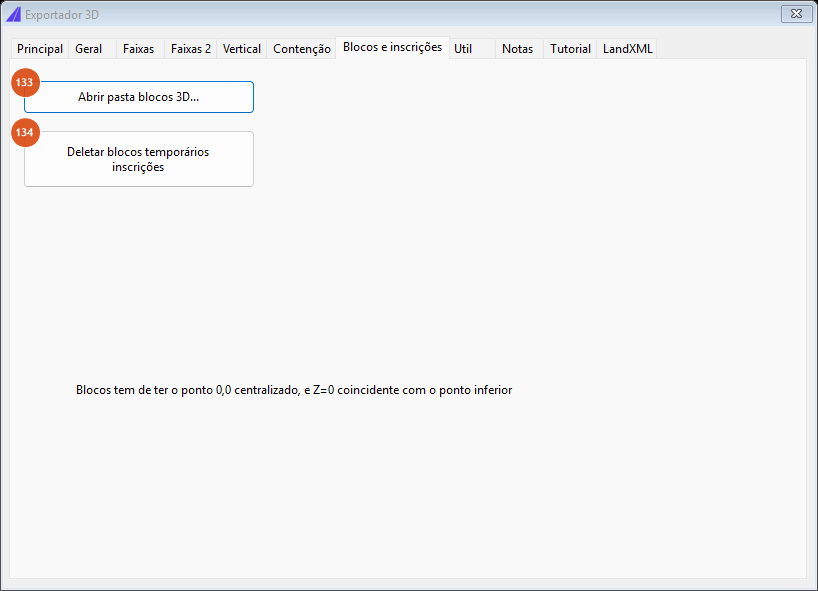
| # | Control | What it does |
|---|---|---|
| 133 | Open the 3D blocks folder… | Opens the local library's 3d sub-folder in Explorer. |
| 134 | Delete temporary legend blocks | Not available in this version. |
The tab's note restates the rule for library 3D blocks: the point 0,0 must be centred and Z = 0 must coincide with the lowest point. (That note is one of the captions that stays in Portuguese.)
Tab 8: Util
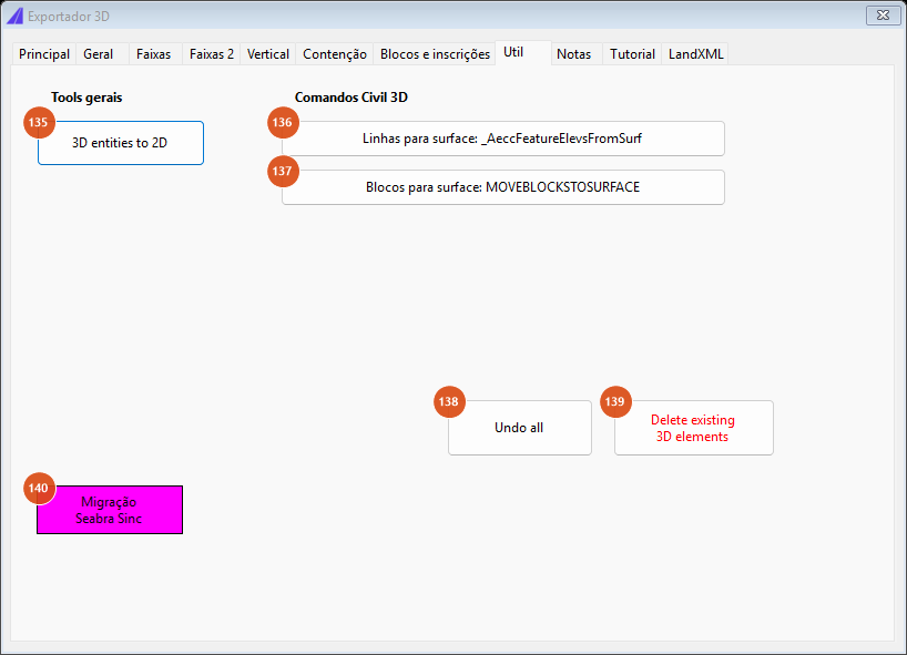
| # | Control | What it does |
|---|---|---|
| 135 | 3D entities to 2D | Not available in this version. |
| 136 | Linhas para surface: _AeccFeatureElevsFromSurf | Shows the list of accepted types (Feature Line, Parcel Segment, Survey Figure, polylines…) and runs the Civil 3D command. |
| 137 | Blocos para surface: MOVEBLOCKSTOSURFACE | Runs the command of the same name. |
| 138 | Undo all | The same as 45. |
| 139 | Delete existing 3D elements | After confirmation, erases from model space every solid, region, 3D face and block whose name ends in 3D, skipping whatever is on an off or frozen layer, and reports how many. |
| 140 | Seabra Sinc migration | Opens the Seabra Sinc → CapCad migration form. |
Tab 9: Notes
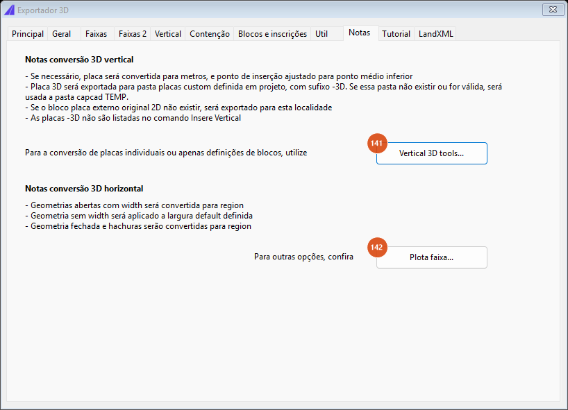
Text only, plus two buttons.
| # | Control | What it does |
|---|---|---|
| 141 | Vertical 3D tools… | Runs CAPCAD_3D_SIGN_CHECK, as 96 does. |
| 142 | Plot line… | Runs CAPCAD_MARKING_SPACING_RENDER. |
Tab 10: Tutorial
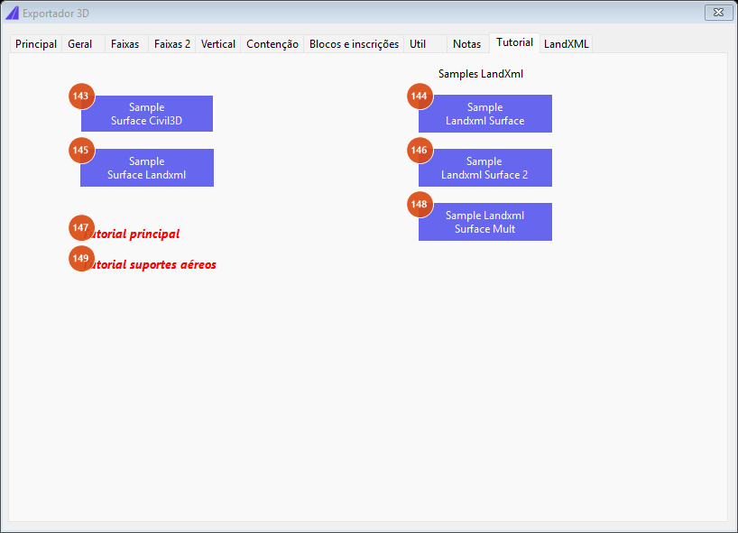
| # | Control | What it does |
|---|---|---|
| 143 | Sample Surface Civil3D | Downloads and opens sample-convert-3d.dwg. |
| 144 | Sample Landxml Surface | Downloads landxml-sample.xml, reads the surface, fills in the path at 10 and reports triangles and points. |
| 145 | Sample Surface Landxml | Downloads and opens sample-convert-3d-nosurface.dwg. |
| 146 | Sample Landxml Surface 2 | Like 144, with landxml-sample-2.xml. |
| 147 | Tutorial principal | Opens the video in the browser. |
| 148 | Sample Landxml Surface Mult | Like 144, with the terrain + road file. |
| 149 | Overhead supports tutorial | Opens the overhead-supports video in the browser. |
Tab 11: LandXML
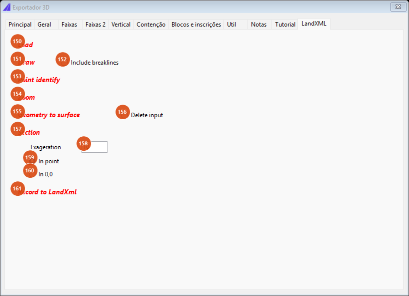
| # | Control | What it does |
|---|---|---|
| 150 | Load | The same as 9: opens the LandXML picker. |
| 151 | Draw | Opens CAPCAD_SURFACE_MANAGER, the surface manager, where these functions were gathered. |
| 152 | Include breaklines | Saved with the form; not used by this version. |
| 153 | Point identify | Opens CAPCAD_SURFACE_MANAGER. |
| 154 | Zoom | Likewise. |
| 155 | Geometry to surface | Likewise. |
| 156 | Delete input | Saved with the form; not used by this version. |
| 157 | Section | Opens CAPCAD_SURFACE_MANAGER. |
| 158 | Exaggeration | Saved with the form; not used by this version. |
| 159 | In point | Saved with the form; not used by this version. |
| 160 | In 0,0 | Saved with the form; not used by this version. |
| 161 | Record to LandXml | Opens CAPCAD_SURFACE_MANAGER. |
How the options combine
The restraint conversion is the part of the assistant whose planning is purely geometric and can be shown without the CAD. The figures below are the engine's own output.
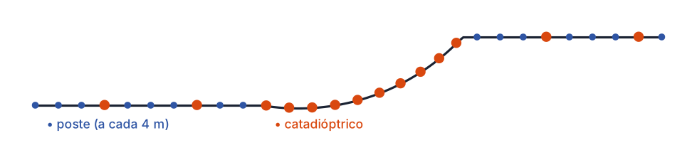
A 110 m path with a curve in the middle, linear step 1: posts every 4 m (blue) and retroreflectors (orange) — every 4 posts along the tangent, thickening to every 1 or 2 posts through the curve, according to the horizontal-curve class at each point. The post spacing is fixed; the retroreflector spacing is not. (The figure's two legend labels are rendered in Portuguese: poste is post and catadióptrico is retroreflector.)

The cross-section of a guardrail (double wave), anchored at its lower centre point. The body is swept along the path, raised 0.5 m above the terrain.
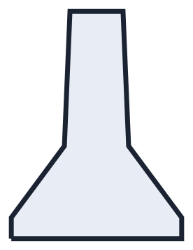
The profile of a double New Jersey barrier. The barrier sits on the terrain, with no lift, and its plan carries neither posts nor retroreflectors.
Lines and blocks depend on the drawing — on the selection, the layers and the library's block definitions — and so have no figure generated here.
Remembered between sessions
The 3D Exporter writes the whole form state on close and reloads it on open — all eleven tabs, fields, boxes and radio buttons. Two exceptions: the surface name is cleared, and the input returns to On screen.
Besides that, the form is a single instance per CAD session: running the command again, or coming in through one of the other forms, brings back the same window with what you left in it. The folder of the last LandXML opened is remembered too.
The items a run created stay in the command's memory until the next run, and that is what Delete last drawn (46) uses.
Notes
- Undo all (45 and 138) is not the inverse of the conversion: it runs the CAD's
UNDOBack, which rewinds to the last mark — possibly past other things you did. Prefer Delete last drawn (46). - The three boxes Insert, Remove and Keep (40 to 42) are saved with the form; not used by this version.
- Ticking Vertical with Overhead supports makes the block pass run even without the Blocks item ticked — restricted to the supports. In the same way, Restraint always runs the block pass, restricted to the restraint accessories.
- The restraint layer filter is a text match on the layer name ("DEFENSA" or "BARREIRA"), in Portuguese, whatever the session language. A guardrail polyline on a layer named otherwise will not be converted.
- When the requested surface cannot be loaded, the assistant writes to the command line that it is using the fixed elevation and carries on — it does not stop.
- Several parameters on the Lines, Lines 2, Vertical, Restraint and LandXML tabs are saved and restored with the form but not used by this version. The tables above mark them one by one.
- A handful of captions have no English text and stay Portuguese in every language: the two Civil 3D buttons on Util (Linhas para surface: _AeccFeatureElevsFromSurf, Blocos para surface: MOVEBLOCKSTOSURFACE), the barrier profile links Baixa and Alta, the Restraint group heading Converter entidades avulsas, the Tutorial principal link, the 3D-blocks note on the Blocks and legends tab, and the three Presets entries (Surface Civil 3D para Infraworks, Configuração recomendada, Outro dwg). They are quoted above as the software shows them.