This page covers the first two tabs of the CapAero form: the one that draws the surface marking of the runway, and the one that repeats a geometry across the pre-threshold area. The remaining tabs (taxiway, apron, reports and tools) are in Airports — Taxiway, Apron and Tools.
| Commands | CAPCAD_AERO_RUNWAY (opens straight on the Runway tab) · CAPCAD_AERO (opens the form on whichever tab it was left) |
| Shortcut | none |
| Ribbon | CapCad tab › Roadway panel › Templates split button › Airport — that button fires CAPCAD_AERO. The four commands that open on a specific tab (CAPCAD_AERO_RUNWAY, _TAXIWAY, _APRON, _SIGN) have no button on the CapCad tab. The airport profile is the exception: it ships a CapAero tab in place of the CapCad one, and its CapAero panel carries all five (Tools, Runway, Taxiway, Apron, Signs) |
| Category | CAPCAD_AERO: CAD Utils: Segment · CAPCAD_AERO_RUNWAY: none |
| Form | AirportForm "CapAero — Airport", nine tabs, modeless. One instance only: running any of the five commands while the form is open just switches tab and brings the window forward |
| Hosts | AutoCAD, BricsCAD, GstarCAD, ZWCAD, ARES Commander |
| Also opened by | CAPCAD_AERO, CAPCAD_AERO_SIGN, CAPCAD_AERO_TAXIWAY and CAPCAD_AERO_APRON — all four open the same form, each on its own tab |
Point at the runway centreline and the whole marking appears — and keeps appearing, redrawn on every value you type.
- A preview that is really live. Every box ticked, every number entered with Enter, erases the previous drawing and draws the new one. You do not run the runway: you tune it while watching it.
- One centreline, five families of mark. Threshold, designation, centre line, touchdown zone and aiming point all come off the same line, each with its own parameters.
- The designation comes from the geography. With the project coordinate system set, the runway number is computed from the true azimuth of the centreline corrected by magnetic variation — and the reciprocal number is shown beside it.
- The aiming point sizes itself from the landing distance available, by banded table; the four computed values are written back into the fields for you to check or overwrite.
- Contrast painting in one click, applied to every mark at once, each family with the rule that suits it.
- The width can come from the landing gear. Type the outer main gear wheel span and the aircraft code, and the runway width is filled in from the table.
What it does
The command opens the CapAero form. On the Runway tab you define the runway centreline — by selecting an existing line or by clicking two points — and from it CapAero assembles the whole surface marking in one pass and draws it.
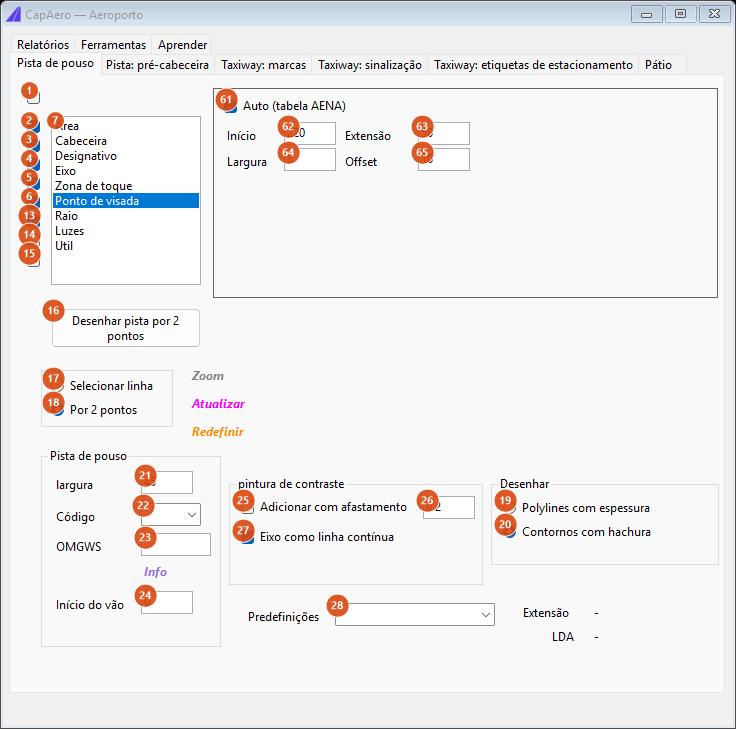
The list on the left (7) holds the runway elements. The tick box beside each row (2 to 6, 13 to 15) says whether that element is drawn; clicking the name swaps the parameter panel on the right without touching the box. The two gestures are independent: you can read the touchdown-zone parameters with the touchdown zone switched off.
The elements are:
| Element | What it draws |
|---|---|
| Area | The runway limits rectangle (layer CAPAERO_RUNWAY_LIMITS), the border lines, and optionally the pre-threshold retention line |
| Threshold | The longitudinal threshold stripes, at both ends, with a central gap |
| Designation | The runway magnetic number and the L/C/R letter, at both ends, in the airport numeral alphabet |
| Center-line | The cadenced centre line, either as a linetype or as drawn rectangles |
| Touchdown zone | The pairs of touchdown-zone bars, in a 3-2-1 pattern or by divisions / fixed spacing |
| Aiming point | The pair of long aiming-point bars |
| Radius | Not available in this version; the panel says so |
| Lights | The edge light points (layers CAPCAD_AERO_LIGHTS_YELLOW and CAPCAD_AERO_LIGHTS_RED) |
| Util | Nothing. The panel only reminds you that Zoom, Update and Reset sit below the draw button |
Everything the runway draws goes to the horizontal-marking layers of the active country profile's catalogue — the white marking layer for the marks and the black one for the contrast painting. The three layers named above are fixed and do not pass through the catalogue.
Live preview
Once the centreline is acquired, any change redraws: ticking or unticking an element, switching a radio button, or typing in a field and pressing Enter. The redraw erases the previous batch before drawing the new one, so the runway is never duplicated. Leaving a field without pressing Enter does not redraw.
Three links sit below the draw button:
- Zoom — not available in this version; the status bar says so.
- Update — erases the last batch and redraws it, useful when something outside the form has touched the drawing.
- Reset — erases the last batch and does not redraw, leaving the drawing clean.
Length and LDA
Bottom right, the form shows two numbers after every draw: Length, the length of the acquired centreline, and LDA, that length minus twice the Gap start (24) — the landing distance available that the automatic aiming-point calculation uses.
Minimum length
CapAero refuses centrelines shorter than 200 m and widths of zero or less: nothing is drawn and the warning appears in the status bar.
Workflow
- Run
CAPCAD_AERO_RUNWAY(orCAPCAD_AEROand pick the Runway tab). - Fill in the width (21). To derive it from the landing gear instead, type the OMGWS (23) and pick the Code (22) — the width is filled from the table.
- Tick the elements you want in boxes 2 to 6 and 13 to 15, or use the top box (1) to switch them all on at once.
- Choose how the centreline is obtained — Select line (17) or By 2 points (18) — and click the button (16), whose caption follows the choice.
- The form hides, you select the line or click the two points, and the runway appears.
- Walk the element list (7) and tune each panel. Every Enter redraws.
- When it looks right, close the form. The drawing stays; the field values are remembered for next time.
The form
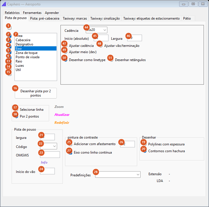
The numbers below apply to the whole page. The right-hand panel changes with the element selected in the list (7); everything else on the tab stays put, which is why controls 1 to 28 appear in every capture.
The screenshots on this page were captured in a Portuguese session; the control numbering is the same in every language, and the tables quote the English captions the form shows in an English session.
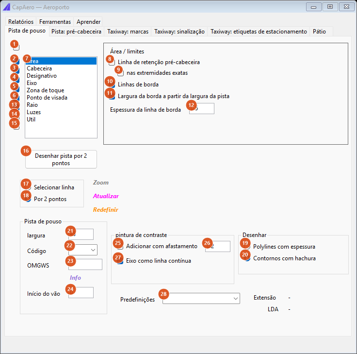
Element Area selected: limits, border lines and pre-threshold retention.
Elements and centreline (common to every panel)
| # | Control | What it does |
|---|---|---|
| 1 | (top box) | Switches the six main elements on or off at once — Area, Threshold, Designation, Center-line, Touchdown zone and Aiming point. Switching it off also unticks Radius and Lights; switching it on does not tick them. Redraws. |
| 2 | (Area box) | Draws the runway limits. While it is unticked, Pre-threshold retention line (8) and Border lines (10) are ignored even when ticked. |
| 3 | (Threshold box) | Draws the threshold stripes at both ends. |
| 4 | (Designation box) | Draws the runway number and letter at both ends. |
| 5 | (Center-line box) | Draws the cadenced centre line. |
| 6 | (Touchdown zone box) | Draws the touchdown-zone bars. |
| 7 | Element list | Swaps the parameter panel on the right. The order is fixed: Area, Threshold, Designation, Center-line, Touchdown zone, Aiming point, Radius, Lights, Util. Selecting an element does not tick it for drawing. |
| 13 | (Aiming point box) | Draws the pair of aiming-point bars. |
| 14 | (Radius box) | Not available in this version. |
| 15 | (Lights box) | Draws the edge light points. |
| 16 | Draw runway… | Acquires the centreline and draws. The caption follows 17/18: Draw runway selecting a line or Draw runway by 2 points. The form hides during the pick. A new centreline makes CapAero "forget" the previous batch — it is no longer erased by later redraws. |
| 17 | Select line | The centreline comes from a line or polyline selected in the drawing. |
| 18 | By 2 points | The centreline comes from two clicks; the second is rubber-banded from the first. |
Draw, runway and contrast (common to every panel)
| # | Control | What it does |
|---|---|---|
| 19 | Polylines with width | Closed marks come out as outline geometry, unhatched. |
| 20 | Boundaries with hatch | Closed marks come out flagged for hatching. This is the default. |
| 21 | width | Runway width, in metres. Every mark is positioned from it. Changing it, with 11 ticked, recomputes the border line width (12). |
| 22 | Code | Aircraft code, 1 to 4. Combined with 23 it gives the width from the OMGWS table. |
| 23 | OMGWS | Outer main gear wheel span, in metres. On leaving the field or pressing Enter, the matching tabulated distance is written into 21 and the runway is redrawn. Combinations outside the table return 0 and leave the width alone. |
| 24 | Gap start | Setback, in metres, from each end of the centreline. It is where the pre-threshold retention starts, it enters the start of the cadenced centre line (added to 45), and it is subtracted twice from the length to give the LDA. |
| 25 | Add with offset | Switches the black contrast painting on for every mark drawn. |
| 26 | (offset) | How far the contrast oversteps the mark, in metres, on each side. Default 0.2. |
| 27 | Centerline as continuous line | Gives the centre line the continuous-strip contrast instead of following the cadence. Ticked by default. |
| 28 | Presets | Three items — 2BRAVO, 2CHARLIE and 3BRAVO. Any of them writes the same three designation values: numeral height 9, letter start 12, numbers start 21. No other field is touched. |
The Info link beside OMGWS opens the table it uses:
| OMGWS | Code 1 | Code 2 | Code 3 | Code 4 |
|---|---|---|---|---|
| < 4.5 m | 18 | 23 | 30 | — |
| 4.5 to 6 m | 18 | 23 | 30 | — |
| 6 to 9 m | 23 | 30 | 30 | 45 |
| 9 to 15 m | — | — | 45 | 45 |
Area element
| # | Control | What it does |
|---|---|---|
| 8 | Pre-threshold retention line | Draws the transverse retention mark at Gap start (24) from each end. Only has effect with 2 ticked. |
| 9 | at the strict ends | Draws the retention at the very ends of the centreline instead of set back. |
| 10 | Border lines | Draws the two longitudinal runway border lines. Only has effect with 2 ticked. |
| 11 | Border width from runway width | Fills 12 automatically whenever 21 changes: 0.5 for runways under 30 m, 0.9 from there up. |
| 12 | Border line width | The width, in metres. The border lines are shifted half a width inwards, so the outer edge of the stripe coincides with the runway limit. |
Threshold element
Threshold stripes are 30 m long, a fixed value. They start at Gap start (24) from each end; if they do not fit (gap start + 30 m longer than the runway), the threshold and the designation on that side are not drawn.
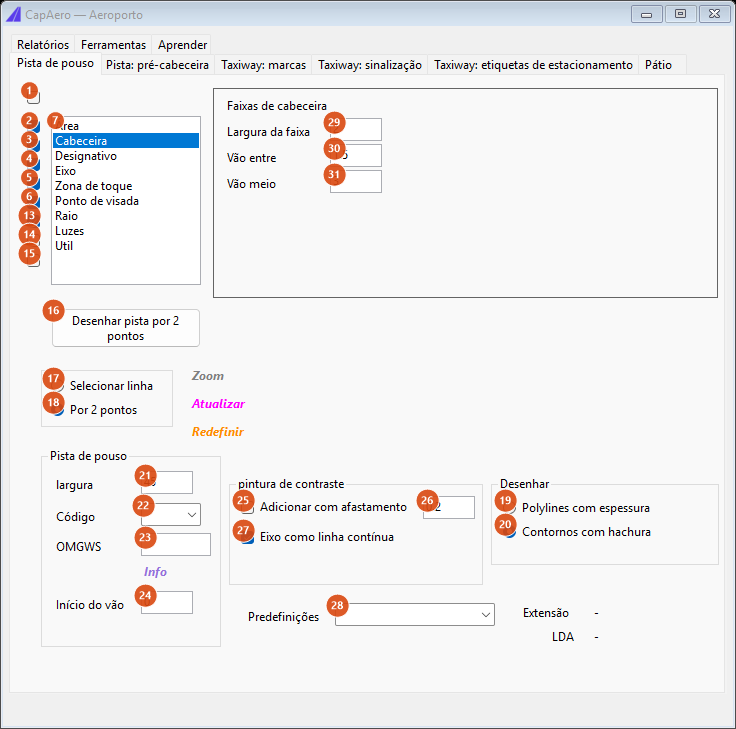
| # | Control | What it does |
|---|---|---|
| 29 | Stripe width | Width of each longitudinal threshold stripe, in metres. Default 2. |
| 30 | Gap between | Gap between neighbouring stripes, in metres. Default 1.5. |
| 31 | Gap middle | Extra gap at the runway centre, separating the two blocks of stripes. Default 3. |
Designation element
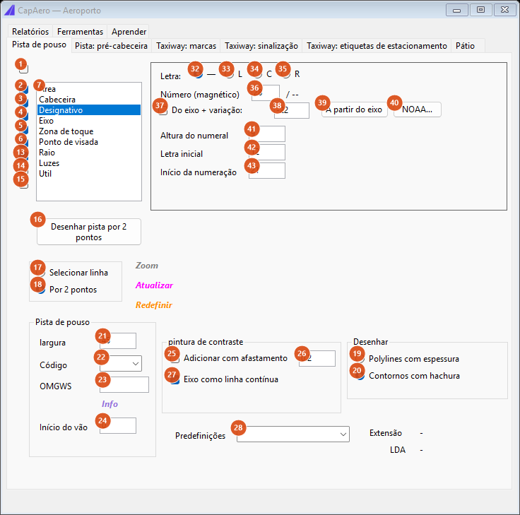
| # | Control | What it does |
|---|---|---|
| 32 | — | No letter: only the number is drawn. |
| 33 | L | Letter L (left) beside the number. |
| 34 | C | Letter C (centre). |
| 35 | R | Letter R (right). |
| 36 | Number (magnetic) | The designation, 1 to 36. As you type, the label beside it shows the opposite threshold's number (number + 18, minus 36 when it overflows); outside 1–36 it shows / --. |
| 37 | From axis + variation | When ticked, the number used in the drawing is recomputed from the centreline on every redraw and the value typed in 36 is ignored. |
| 38 | (variation) | Local magnetic variation, in decimal degrees, west negative. |
| 39 | From axis | Computes the designation now and writes the result into 36, redrawing. Needs an acquired centreline and a project coordinate system; without them it warns in the status bar. |
| 40 | NOAA… | Asks for a point in the drawing, converts it to latitude/longitude, copies the pair to the clipboard and opens the NOAA magnetic-field calculator in the browser. Without a coordinate system it writes the warning to the command line. |
| 41 | Numeral height | Height of the designation characters, in metres. |
| 42 | Letter start | Distance at which the letter begins, measured from the end of the threshold stripe — that is, Gap start (24) + 30 m + this value, counted from the end of the centreline. |
| 43 | Numbers start | The same for the numerals: Gap start + 30 m + this value. |
The designation is the initial azimuth of the great circle between the two ends of the centreline, corrected by the variation, divided by ten and rounded; a resulting azimuth of zero becomes runway 36.
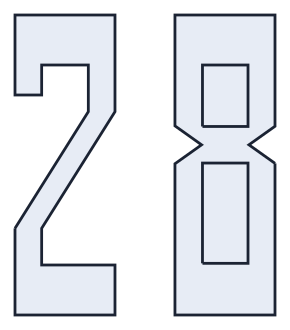
The airport-alphabet numerals, here the pair "28", generated by the engine.
Center-line element
| # | Control | What it does |
|---|---|---|
| 44 | Cadence | Mark × gap of the centre line. Items: 30x20, 1x2, 2x4, 3x6. |
| 45 | Start (absolute) | Distance from the end of the centreline at which the cadence begins. The effective value is this plus Gap start (24). |
| 46 | Width | Constant width of the centre line, in metres. |
| 47 | Adjust cadence | Mark and gap are rescaled so the line begins and ends on a whole mark. |
| 48 | Adjust gap/ending | The adjustment is absorbed by the gap and the ending, keeping the mark. |
| 49 | Adjust middle (dev) | Not available in this version. |
| 50 | Draw as linetype | The centre line comes out as one polyline with the cadence linetype applied. This is the default. |
| 51 | Draw rectangles | Each mark of the cadence comes out as drawn geometry. |
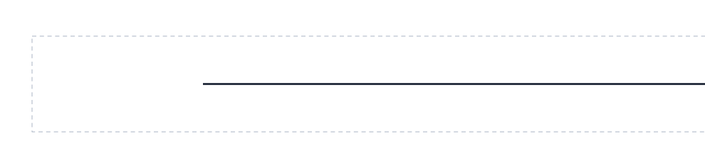
Centre line with Draw as linetype: a single polyline, the cadence living in the layer's linetype.
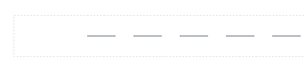
Centre line with Draw rectangles: every mark becomes geometry of its own, measurable and hatchable.
Touchdown zone element
| # | Control | What it does |
|---|---|---|
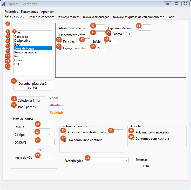
| 52 | Offset from axis | Distance between the centreline and the pair of bars, in metres. Half this value plus half a line width (53) is used. |
| 53 | Line width | Width of each bar, in metres. |
| 54 | Spacing between | Gap between bars of the same group, in metres. |
| 55 | 3-2-1 pattern | The groups have 3, 2 and 1 bars as they move away from the threshold. Ticked by default. |
| 56 | Divisions: | Spreads the groups by number of divisions instead of by fixed spacing. |
| 57 | (number of divisions) | How many divisions, when 56 is chosen. |
| 58 | start | Distance from the threshold at which the division-based spread begins. |
| 59 | Fixed spacing: | Spreads the groups a fixed distance apart. This is the default. |
| 60 | (spacing) | The distance, in metres. Default 122.5. |

Touchdown zone with 3-2-1 pattern and fixed spacing 122.5: the groups lose a bar at every step.

The same runway with Divisions = 4 and start 150: the pairs spread over the length, without the 3-2-1 taper.
Aiming point element
| # | Control | What it does |
|---|---|---|
| 61 | Auto (AENA table) | Computes start, length, width and offset from the LDA and writes the four values back into fields 62 to 65 on every redraw. Ticked by default. |
| 62 | Start | Distance from the threshold at which the bar begins, in metres. |
| 63 | Length | Length of the bar, in metres. |
| 64 | Width | Width of the bar, in metres. |
| 65 | Offset | Distance between the centreline and each bar. Half the width (64) is added to this value. |
The automatic table, by LDA:
| LDA | Start | Length | Width | Offset |
|---|---|---|---|---|
| < 800 m | 150 | 30 | 4 | 3 |
| 800 to 1 200 m | 250 | 30 | 6 | 4.5 |
| 1 200 to 2 400 m | 300 | 45 | 6 | 9 |
| > 2 400 m | 400 | 45 | 6 | 9 |

Aiming point computed for a 2 500 m runway: start 400 m, bars of 45 × 6 m.
Runway: pre-threshold tab
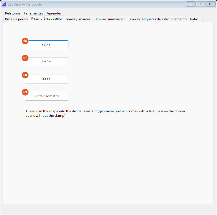
The four buttons load a geometry into the Divider Assistant and apply an airport preset, so all you have to do is point at the path to repeat.
| # | Control | What it does |
|---|---|---|
| 66 | >>>> | Loads the angled mark (a 5 m chevron of width 0.2) into the assistant, with segment 10, extra angle 270°, no ends, on the catalogue's yellow layer. |
| 67 | ^^^^ | Loads the airport entry arrow, in divide mode, with both ends included, extra angle 0 and the white layer. |
| 68 | XXXX | Loads the X mark, extra angle 0, white layer. |
| 69 | Other geometry | Hides the form, asks you to select the geometry to repeat, moves the set so the lower-left corner of its envelope sits on the origin, and loads it into the assistant with no layer preset. |
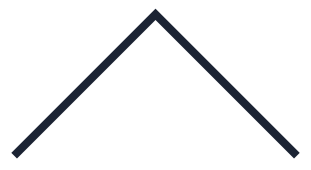
The angled mark of button 66, generated by the engine.
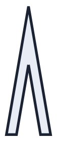
The arrow head of button 67 (the arrow body is not generated by this call).
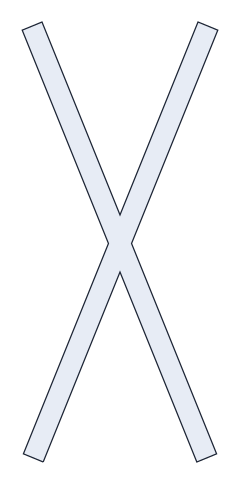
The X mark of button 68.
How the options combine

The first 700 m of a 2 500 × 45 m runway with every element on, designation 28 R, cadence 30x20 and gap start 15 m. Left to right: threshold stripes, designation, the 3-2-1 groups of the touchdown zone, the aiming point (the long bars) and the cadenced centre line — here a single polyline, hence drawn continuous. The dashed rectangle is the limits layer.
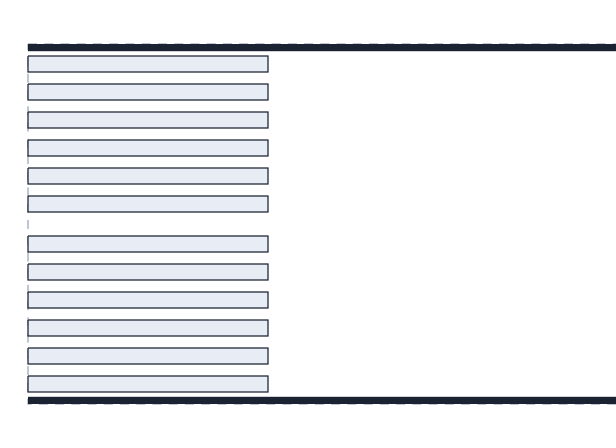
Threshold detail: twelve 2 m stripes separated by 1.5 m, with the 3 m central gap, and the 0.9 m border lines pulled inside the area.
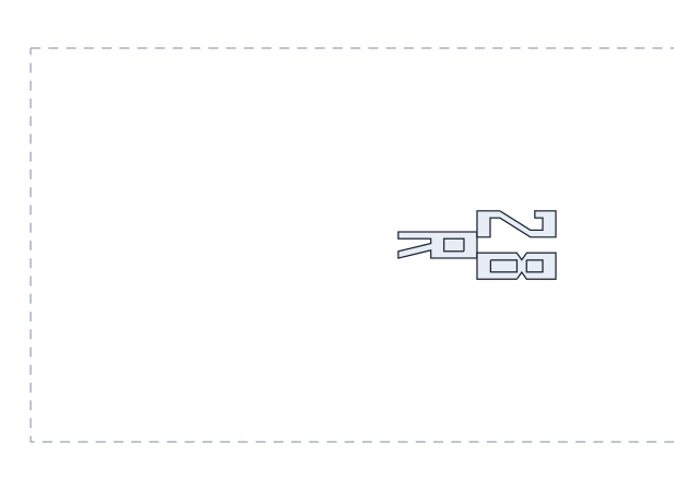
The designation drawn: letter starting 12 m and numerals 21 m after the end of the threshold stripe (here, with gap start zero, at 42 m and 51 m), height 9 m, read from the approach direction.
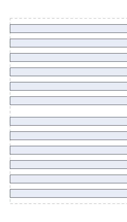
Threshold without contrast painting: the white stripes only (shown light).
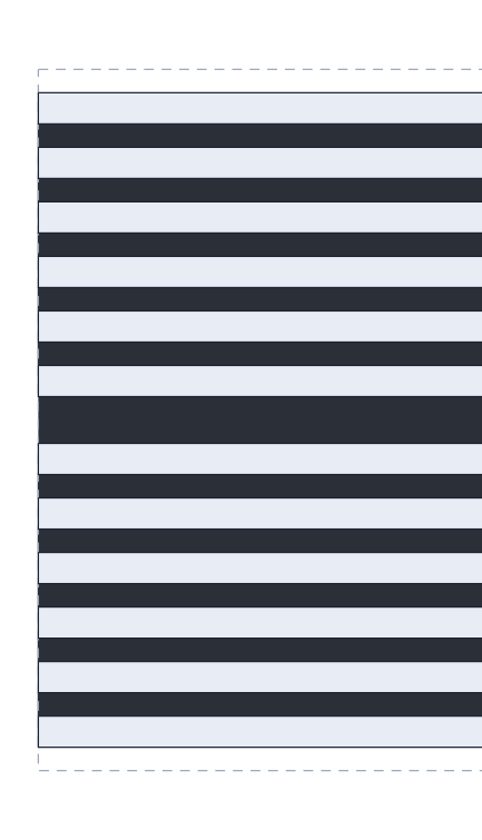
The same threshold with Add with offset ticked: the threshold contrast fills the gaps between the white stripes and adds a wide black stripe on the centreline. Note that the offset (26) is not used here — the contrast width comes from the stripe pitch itself.
Remembered between sessions
On closing the form, CapAero saves the contents of the runway text fields — width, border width, gap start, the three threshold gaps, the three designation fields and the magnetic variation, the centre-line fields, the six touchdown-zone fields and the four aiming-point fields — and reloads them the next time it opens. Tick boxes, radio buttons and combos are not remembered: they return to the form defaults.
The acquired centreline is not remembered: reopening CapAero means pointing at the runway again.
Notes
- The draw button replaces the previous drawing only while the centreline is the same. Acquiring a new centreline makes the command forget the previous batch, which becomes part of the drawing like any other geometry.
- The Radius element is not available in this version; its panel says so instead of offering parameters.
- The parameter panel is chosen by the position of the item in the list, not by its text, so translating the interface does not misalign the panels.
- The three Presets (28) write exactly the same values. They do not distinguish runway category.
- The minimum-length warning (200 m) and the other warnings appear in the form's status bar, one at a time — the last one raised.
- The Zoom link is not available in this version.
- The centre-line contrast, when Centerline as continuous line (27) is ticked, is generated from a copy of the centre line and does not replace the white mark.
- The marks go to the white and black horizontal-marking layers of the active country profile's catalogue.
CAPAERO_RUNWAY_LIMITS,CAPCAD_AERO_LIGHTS_YELLOWandCAPCAD_AERO_LIGHTS_REDare fixed names and do not pass through the catalogue. - Pressing Enter in fields on other tabs (sign letter size, label colours, arrow size) also fires the runway redraw.