| Commands | CAPCAD_CIVIL3D_TOOLS (Civil 3D utilities) · CAPCAD_GEOMETRY_TOOLS (not available in this version — see the last section) |
| Shortcut | none |
| Ribbon | CAPCAD_CIVIL3D_TOOLS: CapCad tab › BIM panel › 3D split button › Civil3D Utils. CAPCAD_GEOMETRY_TOOLS has no button in any country profile |
| Categories | CAPCAD_CIVIL3D_TOOLS: CAD Utils: Segment · CAPCAD_GEOMETRY_TOOLS: Manage: Tools |
| Form | Civil3DUtilitiesForm — Civil 3D Utilities, modeless, single instance (running the command again brings the open window forward), four tabs |
| Hosts | CAPCAD_CIVIL3D_TOOLS: registered in AutoCAD; the window only opens when Civil 3D is loaded (otherwise the command warns and exits). On ARES it reports itself as coming soon; it does not exist in BricsCAD, GstarCAD or ZWCAD. CAPCAD_GEOMETRY_TOOLS: registered in AutoCAD and ARES, and on both it only shows a warning |
| Also opened by | CAPCAD_RAILWAY opens this same window; so does the Civil 3D navigation button on the Road width form (CAPCAD_ROAD_WIDTH) |
The geometric design lives in Civil 3D; the signing is done in CapCad. This window is the bridge — and it crosses both ways.
- The Civil 3D alignment becomes the project's alignment. One alignment, or all of them at once, converted with the tangents, curves and spirals preserved.
- The vertical comes with it. The Civil 3D profile is sampled and written into the alignment, with the PVIs and the geometry points; and if the alignment has a single profile, it is set on its own during the load.
- The profile queried in plan. Click a point on the alignment and read the station, the elevation, the local grade and the previous and next PVI — without leaving the plan view.
- Notable points become signs. TC, CT, SC, CS on the horizontal; PCV, PTV and PIV on the vertical — as markers, or as kilometre-post-style sign blocks already inserted in both directions.
- Surface work without leaving CapCad. Elevation at a point, grade between two, cross slope across the alignment, an extracted section and a 3D polyline of the alignment draped on the terrain.
- Cleaning a heavy drawing. Freeze by Civil 3D object family, purge unused styles and open a clean dwg already in metres.
What it does
CAPCAD_CIVIL3D_TOOLS opens a modeless window with four tabs:
- Alignment & profile — load the alignment and the profile from Civil 3D into the CapCad project, draw them, frame them, query the profile and draw grades and notable points on the alignment.
- Surface — load Civil 3D TIN surfaces and query them: elevation, grade, section, drape.
- Tools — freeze layers by object type, purge styles, turn the geographic map off, open an empty dwg and call the COGO point conversion.
- Property Sets — install and attach the active style's property sets, and choose between the 2D and the 3D set in this drawing.
The command is registered in plain AutoCAD, but it checks for Civil 3D before showing the window: without it, it warns that Civil 3D is not loaded and ends. The same window works on any Civil 3D version CapCad recognises.
Workflow
Bringing alignment and profile from Civil 3D
- Open the drawing in Civil 3D and run
CAPCAD_CIVIL3D_TOOLS. - On the Alignment & profile tab, choose the alignment in Alignments (1). The list carries the drawing's alignments plus the entry
<all>, meaning "every one". If the project's alignment already has the name of one of them, it comes pre-selected; otherwise<all>does. - Click Load (2). The alignment becomes the CapCad project's alignment. With
<all>, the alignment file takes the drawing's name; with a single one, the alignment's name. - If you chose one alignment (not
<all>) and it has exactly one profile, that profile is set in the same click, and CapCad says so. - Otherwise, choose the profile in Profiles (7) and click Load (8). The combo is disabled while
<all>is chosen — a profile belongs to one alignment only. - Draw (3 and 10) and Zoom (4 and 11) work on the alignment and profile already written into the project.
Querying the profile from the plan view
- With alignment and profile set, click Identify profile data in alignment (13).
- Click a point on the alignment — the command projects the point onto the alignment, converts it to a station and reads the profile there.
- The command line answers with the station, the elevation, the local grade and the stations of the previous and next PVI.
- The command repeats until you press Esc. A point that does not project onto the alignment is reported and ignored.
Drawing the profile's grades on the alignment
- Click Draw profile slopes on alignment (14).
- Each straight stretch of the profile is converted into a start and end station, and the matching piece of the alignment in plan is drawn on a layer named
CAPCAD_RAMPAfollowed by the grade value —CAPCAD_RAMPA-3.50,CAPCAD_RAMPA5.20… — all in colour 53. - Uphill grades are drawn reversed, so that the drawing-direction arrow points downhill.
- Nothing is flagged as critical here: this button only plots every grade.
Notable points of the alignment and the profile
| Button | What it draws |
|---|---|
| Draw alignment geometry points (15) | A POINT at each segment transition of the alignment, on layer CAPCAD_ + the label (CAPCAD_TC, CAPCAD_CT, CAPCAD_SC, CAPCAD_CS, CAPCAD_ST…), each label with its own colour |
| Signs at horizontal notable points (17) | A sign block named MR_ + label at each of those transitions, offset 4 from the alignment, in both directions (one increasing pass and one decreasing) |
| Draw profile geometry points on alignment (16) | A POINT on CAPCAD_PCV and CAPCAD_PTV at the start of each vertical curve and each tangent of the profile, and one on CAPCAD_PIV at each PVI — all projected into plan by station |
| Signs at vertical notable points (18) | Sign blocks MR_PCV, MR_PTV and MR_PIV at the same points, plus an ID-07 block after each PVI, offset 40, with the in and out grades and the neighbouring lengths in the attributes INCL1, KM1, INCL2 and KM2 |
All four depend on the alignment (or the profile) having been loaded from Civil 3D by this window: it is the segment data and the PVIs brought in by the conversion that feed the labels. An alignment drawn by hand has no such data, and the command says so.
Working with the surface
- On the Surface tab, choose the scope (24 to 26) and click Load (23).
- With the surface loaded, the left-hand buttons answer on the command line, in a loop, until Esc:
- Find the surface elevation (27) — the elevation of the clicked point, the highest among the loaded surfaces.
- Find the surface slope (28) — two points, the grade between the two terrain elevations.
- Find the surface slope across the alignment, 1 pt (29) — one point only: CapCad builds a 1 mm chord perpendicular to the alignment there and measures the cross slope. The result comes out in a box, not on the command line.
- Extract section (31) uses the bottom frame to know how to define the cut line: two points (34), a line in the drawing (35) or a cross-section of the alignment with the width from 36 (37, the default). Vertical exaggeration (33) multiplies the elevation axis of the drawn section.
- Break the line at the surface's points (30) drapes a chosen curve on the surface and draws a 3D POINT at each crossing with the TIN, on layer
CAPCAD_PLAN_POINTS. - Generate 3D polyline from alignment and surface (39) does the same with the project's alignment and returns one 3D POLYLINE per element.
Cleaning the drawing
- On the Tools tab, tick the families you want hidden (40 to 44) and click Freeze (45). The layers actually frozen show up in the read-only box (46).
- Purge unused styles (47) runs Civil 3D's
PURGESTYLESthree times, answering Yes — the native command does not clean everything in one pass. - Geo map off (48) turns the background geographic map off.
- New emtpy dwg (49) creates a new drawing and forces the insertion units to metres.
- COGO points conversion… (50) fires
CAPCAD_POINT_TO_COGO.
The form
The numbers are unique on this page: 1 to 21 on the Alignment & profile tab, 22 to 39 on Surface, 40 to 50 on Tools and 51 to 57 on Property Sets. The screenshots are of a Portuguese session; the numbering is the same in both editions, and the tables give the English captions.
Tab 1: Alignment & profile
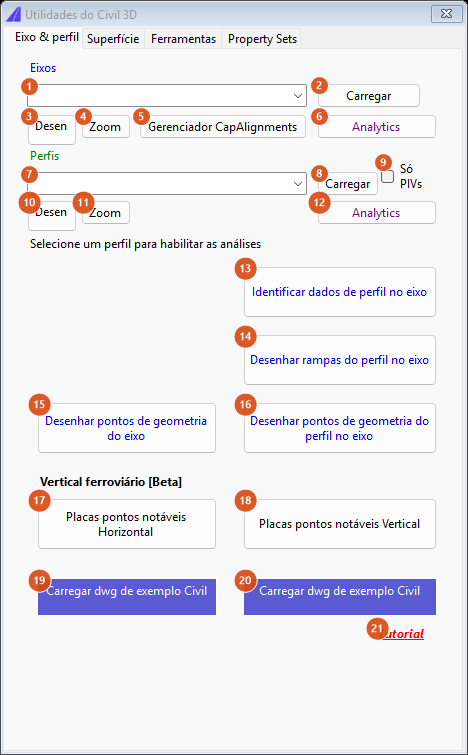
| # | Control | What it does |
|---|---|---|
| 1 | Alignments | The drawing's alignments, plus the <all> entry |
| 2 | Load (alignments) | Converts the chosen alignment — or all of them — into the CapCad project's alignment |
| 3 | Draw | Draws the project's alignment in the drawing |
| 4 | Zoom | Frames the project's alignment |
| 5 | CapAlignments Manager | Opens the Alignment Manager |
| 6 | Analytics (alignment) | Fires the horizontal sight-distance analysis |
| 7 | Profiles | The profiles of the alignment chosen in 1. Disabled with <all> |
| 8 | Load (profiles) | Converts the profile and writes it into the project's alignment. With the field blank, it uses the first profile in the list |
| 9 | Only PVIs | Imports the PVI polygon only — the vertical alignment without the vertical curves. The PVI and geometry-point data are still written, so buttons 16 and 18 work just the same |
| 10 | Draw | Draws the elements of the stored profile |
| 11 | Zoom | Frames the profile |
| 12 | Analytics (profile) | Fires the profile analyses |
| 13 | Identify profile data in alignment | A click loop in plan: station, elevation, local grade and the neighbouring PVIs |
| 14 | Draw profile slopes on alignment | Plots each straight stretch of the vertical alignment over the alignment, on one layer per grade value |
| 15 | Draw alignment geometry points | POINTs at the TC / CT / SC / CS transitions of the alignment |
| 16 | Draw profile geometry points on alignment | POINTs at the PCV, PTV and PIV, projected into plan |
| 17 | Signs at horizontal notable points | The same transitions, as MR_* sign blocks, in both directions |
| 18 | Signs at vertical notable points | PCV / PTV / PIV as sign blocks, plus one ID-07 per PVI with the grades and lengths |
| 19 | Load Civil 3D Sample dwg | Asks, downloads and opens the sample drawing |
| 20 | Load Civil 3D Sample dwg spiral | The same, in the version with spirals |
| 21 | Tutorial | Opens the Civil 3D video on YouTube |
The two notable point sign buttons sit under the heading Railway vertical [Beta], but they are not restricted to a railway project.
Tab 2: Surface
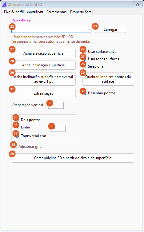
| # | Control | What it does |
|---|---|---|
| 22 | Surfaces | The drawing's TIN surfaces. If there is only one, it is chosen on its own |
| 23 | Load | Reads the surface (or surfaces) into memory according to the scope of 24 to 26 |
| 24 | Use the active surface | Loads the surface named in 22 — see Notes |
| 25 | Use every surface | Loads every surface in the drawing. Ticked by default |
| 26 | Select | Identical to 24 in this version |
| 27 | Find the surface elevation | A click loop: the highest elevation among the loaded surfaces, at each point |
| 28 | Find the surface slope | A loop of click pairs: the grade between the two terrain elevations |
| 29 | Find the surface slope across the alignment, 1 pt | One click: the cross slope, measured on a 1 mm chord perpendicular to the alignment |
| 30 | Break the line at the surface's points | Drapes a chosen curve and draws a 3D POINT at each crossing with the TIN, on layer CAPCAD_PLAN_POINTS |
| 31 | Extract section | Cuts the surface along the line defined in frame 34–37 and draws the section |
| 32 | Draw points | Saved with the form; not used by this version |
| 33 | Vertical exaggeration | Multiplies the section's elevation axis. Default 1; invalid text also falls to 1 |
| 34 | Two points | The cut line comes from two clicks |
| 35 | Line | The cut line is a curve in the drawing |
| 36 | (width) | The width of the cross-section, in drawing units. Default 10 |
| 37 | Across the alignment | The cut line is a cross-section of the alignment, centred on the clicked point, with the width from 36. Ticked by default |
| 38 | Add grid | Not available in this version. |
| 39 | Generate 3D polyline from alignment and surface | Drapes the project's alignment on the surface and draws one 3D POLYLINE per element |
Tab 3: Tools
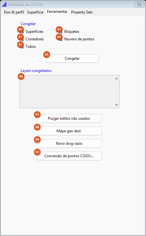
| # | Control | What it does |
|---|---|---|
| 40 | Surfaces | Includes TIN, grid and data-shortcut surfaces |
| 41 | Corridors | Includes corridors, baselines, regions, assemblies and subassemblies |
| 42 | Pipes | Includes pipe and pressure networks, structures, connections and appurtenances |
| 43 | Labels | Includes label groups and styles, contour labels, COGO points, point groups, survey figures and proxy entities |
| 44 | Point clouds | Includes the point clouds |
| 45 | Freeze | Freezes the layer of every entity falling into one of the ticked families |
| 46 | Frozen layers: | The read-only list of what was frozen on this run |
| 47 | Purge unused styles | Runs Civil 3D's PURGESTYLES three times in a row, answering Yes |
| 48 | Geo map off | Turns the background geographic map off (GEOMAP → Off) |
| 49 | New emtpy dwg | Creates a new drawing and sets the insertion units to metres |
| 50 | COGO points conversion… | Fires CAPCAD_POINT_TO_COGO |
The five boxes are born ticked. The current layer is never frozen — AutoCAD refuses — and so it does not appear in the list at 46 either.
Tab 4: Property Sets
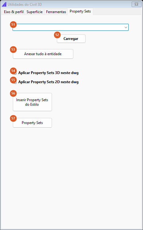
| # | Control | What it does |
|---|---|---|
| 51 | (property set source) | The .capstyle and .dwg files in the propsets folder of CapCad's support |
| 52 | Load | Re-reads the folder and repopulates the list |
| 53 | Attach all to entity | Asks for an entity and attaches to it every property set defined by the drawing's active style, in one go |
| 54 | Apply 3D Property Sets in this dwg | Writes into the drawing the mark that this is a 3D drawing. Ticking one unticks the other |
| 55 | Apply 2D Property Sets in this dwg | The mirror of 54 |
| 56 | Insert the Style's Property Sets | Installs the property set definitions in the drawing, from the source in 51 (or from the style, if 51 is blank) |
| 57 | Property Sets | Opens the property set manager |
How the options combine
What the conversion brings with the geometry
The profile load (8) does not keep only the vertical alignment's line. It also writes into the project's alignment:
| Datum | What it is for |
|---|---|
pviCol |
Each PVI with its in grade, out grade and neighbouring lengths — this is what feeds 13, 16 and 18 and the ID-07's attributes |
geometryPoints |
The station at which each curve and each tangent of the profile starts — the PCV and PTV |
| Profile anchor | The X and Y of the first vertex in the profile view, plus the start station: this is what turns a drawing coordinate into a station |
| Original vertical scale | The vertical exaggeration of Civil 3D's own profile view — stored, but not used when reading; see Notes |
With Only PVIs (9) ticked, the line drawn becomes the PVI polygon, without the vertical curves, but the first three rows of the table are still written the same.
The profile's vertical exaggeration is treated as real length
The Civil 3D profile is stored in drawing coordinates: x = station, y = elevation × the view's exaggeration. On reading, however, CapCad always divides by 10.
That has two consequences:
- In Draw profile slopes on alignment (14), the length each stretch is compared against the limits in metres is the 2D length of the drawn stretch, that is, already stretched by the exaggeration. A stretch of 100 m in projection at 5 % grade measures, in a drawing at 10×, about 112 m. Stretches under 10 drawing units are discarded before any arithmetic.
- In Identify profile data in alignment (13), the elevation returned is
y ÷ 10without subtracting the profile view's origin: it is only the true elevation when the view's elevation zero sits aty = 0of the drawing. The grade, being a difference, does not suffer from this.
In both cases, the right number comes out when the Civil 3D profile view is at exaggeration 10. See Notes.
Surface scope: which one each button uses
| Button | Uses |
|---|---|
| Find the surface elevation (27) and Find the surface slope (28, 29) | The highest elevation among every loaded surface |
| Extract section (31) | Every loaded surface, one section per surface |
| Break the line (30) and 3D polyline (39) | Only the first loaded surface |
If you use Use every surface (25) in a drawing with both existing ground and design surfaces, it is worth checking which one ended up first before draping.
Remembered between sessions
Nothing. The window writes no options to the preferences. Being single-instance, though, what you chose stays there while AutoCAD is open: closing it and running the command again reopens the same window, with the same combos, radios and boxes. The loaded surfaces also survive between openings of the window, within the same session.
The only thing written to the file is the choice between 2D and 3D Property Sets (54/55), which goes into the drawing's own configuration.
CAPCAD_GEOMETRY_TOOLS — not available in this version
This command is not available in this version. Running it in AutoCAD only opens a box saying so.
Two points that usually cause confusion:
- It has no ribbon button in any country profile.
- The ribbon button labelled Geometry Tools, on the CAD Utilities panel, is a different command. It fires
CAPCAD_ROAD_LANE, the lane assistant — the tooltip says Lanes.
If you are after geometry tools, what exists today is spread between the Alignment Manager, the alignment tools and the drawing utilities.
Notes
- The window needs Civil 3D, not just AutoCAD. The command is registered in plain AutoCAD so that it can give the right message, but it ends before showing the window when Civil 3D is not loaded. It does not exist in BricsCAD, GstarCAD or ZWCAD.
- The reading exaggeration is fixed at 10. Identify profile data in alignment (13) and Draw profile slopes (14) always divide by 10. On a profile view built at another exaggeration, the elevation and grade those two report come out proportionally wrong.
- If CapCad cannot read the profile view, the vertical alignment comes out flat. In that case the vertical scale is stored as zero and every elevation of the converted profile becomes
y = 0. A profile that appears as a horizontal straight line is the symptom. - Grade lengths are measured on the stretched drawing. See How the options combine: the grade limits in metres are compared against the 2D length of the already-exaggerated stretch, and stretches under 10 drawing units are discarded. Nothing is flagged critical on this button anyway — the threshold used here is unreachable by design.
- The grades and the vertical signs only see the alignment's first element. Draw profile slopes (14) maps the profile's stations onto the alignment's first element, and the signs of 18 take their insertion angle from that same first element's tangent. On a project alignment made of several elements — the case for anyone who loaded
<all>— whatever falls outside the first element is not drawn, or comes out at the wrong angle. Load one alignment at a time when you use those two buttons. - The grade and notable-point layers keep fixed names.
CAPCAD_RAMPA…,CAPCAD_TC,CAPCAD_PIV,CAPCAD_PLAN_POINTSand company are created under those names, in a fixed colour. They do not get the active style's prefix or renaming, unlike the rest of the drawing. - "Use the active surface" and "Select" do the same thing. Both load the surface named in the combo (22); in this version there is no concept of an active surface separate from the combo's choice. Only Use every surface (25) behaves differently.
- Two boxes on the Surface tab are not used. Draw points (32) is saved with the form but not used by this version; Add grid (38) is not available in this version.
- The notable points depend on the conversion. 15 to 18 read the segment and PVI data that the Civil 3D load writes into the alignment. On an alignment assembled from CAD curves that data does not exist, and the command warns instead of drawing anything.
- The horizontal signs are inserted in both directions. Signs at horizontal notable points (17) makes one increasing pass and one decreasing pass, so each transition gets two signs.
- The style purger runs three times. It is not a mistake: Civil 3D's
PURGESTYLESdoes not clean everything in one pass, and CapCad repeats it three times answering Yes. - A number of the window's messages are not translated: the command-line summaries, the surface warnings and the "reload from Civil 3D" texts.