| Commands | CAPCAD_RESTRAINT (the Road restraint form) and CAPCAD_BATCH_RESTRAINT (batch insertion) |
| Shortcut | DEF for CAPCAD_RESTRAINT; the batch insertion has none |
| Ribbon | CapCad tab › Safety panel › Restraint split button › Defensa & Barreira and Inserir Defensa em Lote |
| Category | Safety for CAPCAD_RESTRAINT; the batch insertion is mapped as Horizontal: tools |
| Forms | DefensaForm — "Road restraint", 7 tabs; DefensaBatchForm — "Defensa Batch Insert". Both are modeless: you click points in the drawing with them open |
| Hosts | CAPCAD_RESTRAINT: AutoCAD, BricsCAD, GstarCAD, ZWCAD, ARES Commander. CAPCAD_BATCH_RESTRAINT: AutoCAD |
| Also opened by | none. The stretch table produced by CAPCAD_ANALYTICS_RESTRAINT is the natural input of the batch insertion |
A guardrail is a parallel of the alignment with a length that is a whole number of beams and a terminal at each end — and that is what this command delivers in one go. With OFFSET, TRIM and INSERT you do the same thing in five steps and still have to check the metreage.
- Four ways of saying where. Two clicked points, one point plus a length, a station plus a length, or station to station — whichever is closest to your design table.
- Metreage that closes. Offsetting from the alignment changes the length through a curve; the body is re-anchored at the start point and rounded to whole beams.
- Room for the terminals. The body can pull back 12 m at each end so that the terminal blocks occupy the extremities without overlapping the rail.
- Terminals with attributes. The blocks are brought from the library, scaled, rotated and stamped with station, span and function; whatever is not found is named in the report, not silently dropped.
- The embankment hatch with it. The slope hatch can be drawn in the same pass, offset from the body by the value you give.
- From the report to the drawing. The batch insertion reads the table in stations or in coordinates and draws a whole road's worth at once, with a layer per action.
What it does
CAPCAD_RESTRAINT draws a lateral restraint device — a metal guardrail, a concrete barrier or a generic object — as a polyline parallel to the alignment, plus the two terminal blocks at the ends.
The chain is always the same:
- Two points. The positioning method you chose produces a start and an end point: clicked, or computed from a station and a length.
- Projection onto the alignment. The two points are projected perpendicularly onto the alignment (a 500-unit reach) and ordered by station.
- The stretch. The part of the alignment between the two stations becomes the device's reference line.
- The offset. That stretch is shifted sideways by the offset. A positive offset draws the body to the right of the alignment's increasing direction (CapCad calls that Increasing); Decreasing puts it on the left.
- The metreage. Through a curve, the parallel comes out longer or shorter than the alignment stretch. The body is then re-anchored at the start point and rounded to the object's multiple: 4 m (one beam) for the guardrail and for the custom object, 1.50001 m for the barrier — the extra 0.00001 keeps the length from landing exactly on a linetype pattern boundary.
- Terminal clearance. If the terminals must not overlap the body, it shrinks by 24 m — three 4 m beams at each end — so that the blocks occupy the extremities.
- The terminals. Two blocks are placed at the ends of the body, facing outwards, scaled and stamped.
The body is drawn on the current layer. The batch insertion, and only it, resolves the layer from the action (DEFENSA_IMP, DEFENSA_MAN, DEFENSA_REM, DEFENSA_SUB of the active layer catalogue).
The Info tab of the form carries the glossary of terminal abbreviations the project uses, taken from the norm of the active country profile. The abbreviations are the ones the shipped block library is named after; the same glossary is behind See the accepted values (129) on the batch form.
Workflow
- Run
CAPCAD_RESTRAINT(or typeDEF). The form opens beside the drawing. - On the Main tab, choose the positioning method (2, 3, 5 or 8) and fill its boxes. Clicking inside a box already selects the method it belongs to.
- Choose the object (27, 28 or 29) and the offset: Detect from the point (11) measures the distance from the clicked point to the alignment, or Fixed (12) uses the value in 13.
- Adjust the terminals (1, 16 to 20) and the body action (48, 49, 51, 52).
- Click Insert (40).
- In the point methods, the command asks for Ponto inicial and, in 2 points, also for Ponto extensão.
- The command asks you to select the alignment — a polyline or a line.
- The body is drawn, the embankment hatch is added if Add slope (54) is ticked, the terminal blocks are inserted, and the command line sums it up: body length, start and end station, direction, and how many terminals went in out of how many were planned.
The form stays open for the next stretch.
The Road restraint form
Numbers 1 to 95 run through the seven tabs of Road restraint; 96 to 132 are the batch insertion, further down. The screenshots are of a Portuguese session; the numbering is the same in both editions, and the tables give the English captions.
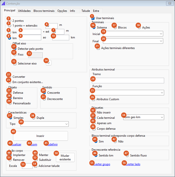
The Main tab, the form as it opens: method km to km, object Barrier, direction Increasing, action Insert.
Tab 1: Main
Positioning method (top left frame)
| # | Control | What it does |
|---|---|---|
| 2 | 2 points | The command asks for two points in the drawing; they are projected onto the alignment and bound the stretch. |
| 3 | 1 point + length: | The command asks for one point; it gives the start station, and the end is that station plus the length in 4. |
| 4 | length (default 32) | Method 3's length, in metres — or in beams, if Beams (=4m) (84) is ticked, when each unit is worth 4 m. Typing here already selects method 3. |
| 5 | km (+ length) | Start station in kilometres in box 6, plus the length in box 7. A zero in either is refused, so a stretch starting exactly at km 0+000 cannot be typed. |
| 6 | start km | In kilometres (the command multiplies by 1,000). |
| 7 | length (default 32) | Method 5's length, in metres or in beams. |
| 8 | km (to km) | Start station in box 9 and end station in box 10, both in kilometres. It also refuses zero. This is the default method. |
| 9, 10 | start km, end km | In kilometres. |
| 22 | Convert | Turn an existing polyline into a restraint body. Not available in this version: the command says so on the command line. |
| 23 | In existing assembly… | Add to an assembly already drawn. Not available in this version: the command says so. |
In both km methods, the command frames the view on the resolved stretch.
Alignment offset
| # | Control | What it does |
|---|---|---|
| 11 | Detect from the point | The offset is the distance from the clicked point to the alignment. It only makes sense in methods 2 and 3, which have a clicked point; in the km methods there is no point to measure from and the value in 13 is used. |
| 12 | Fixed: | Uses the value in box 13 as the offset. |
| 13 | fixed offset | Distance from the alignment, in drawing units. The box is disabled while Detect from the point is ticked. Default 8. |
| 14 | ⟳ | No effect in this version. |
| 15 | Select alignment | No effect in this version: the command always asks for the alignment when you click Insert. |
In the point methods, the side of the clicked point decides the direction: a point to the left of the alignment makes the stretch Decreasing, one to the right, Increasing. Buttons 30 and 31 apply to the km methods.
Object, Direction, Characteristics
| # | Control | What it does |
|---|---|---|
| 27 | Guardrail | Metal guardrail: length rounded to multiples of 4 m. |
| 28 | Barrier | Concrete barrier: multiples of 1.50001 m. It is the form's default. |
| 29 | Custom | A generic object; it rounds like the guardrail, in multiples of 4 m. |
| 30 | Increasing | Body to the right of the alignment's increasing direction. |
| 31 | Decreasing | Body to the left, and the offset goes in with a negative sign. |
| 37, 38 | Single, Double | No effect in this version. |
| 39 | Type | No effect in this version; the list is empty. |
Body action, scale and slope
| # | Control | What it does |
|---|---|---|
| 48, 49, 51, 52 | Insert, Keep, Remove, Replace | The stretch's action. It is inherited by both terminals unless Different terminal actions (21) is ticked, and it chooses which terminal block is used when Differentiate status (78) is on. In the batch insertion it is what chooses the layer. |
| 50 | Change existing | No effect in this version. |
| 53 | Scale | Scale of the terminal blocks. Empty, zero or negative counts as 1. |
| 54 | Add slope | After drawing the body, draws the embankment hatch from it, with the four values of the Slope tab (88 to 91). |
Terminals (right column)
| # | Control | What it does |
|---|---|---|
| 1 | Use terminals | Unticked, no terminal block is resolved or inserted, and the command line reports that terminals are off. The Terminals and Terminal attributes frames are disabled with it. |
| 16 | System | The type typed in boxes 19 and 20 is used as a block name. With both boxes empty — the initial state — the names come out empty and no terminal is found. |
| 17 | Blocks | Uses the names from the Terminal blocks tab (81 and 82), varied by action if Differentiate status (78) is ticked. Ticking this option also switches off the 24 m pull-back described in 42. |
| 18 | Actions | Neither type nor name: both terminals use CapCad's default block, DEF_TERMINAL_IMP. |
| 19, 20 | Start, End | Free text boxes (the lists come empty). Under System they are the block names. |
| 21 | Different terminal actions | Unticked, both terminals inherit the body's action. Ticked, each terminal has its own action — but the per-terminal options are not available in this version, so in practice both still follow the body's action. |
| 24 | Span | No effect in this version. |
| 25 | Function | No effect in this version; the list is empty. |
| 26 | Custom attributes | No effect in this version. |
Labels
The whole frame is not available in this version: nothing is written beside the guardrail.
| # | Control | What it does |
|---|---|---|
| 32 | Do not insert | No effect in this version. |
| 33 | Each terminal | No effect in this version. It is the option ticked by default, and the only one that shows list 34. |
| 34 | label style | Two options, term geo km and acao term geo km. It only appears with 33 ticked. No effect in this version. |
| 35 | Only one | No effect in this version. |
| 36 | Guardrail body | No effect in this version. |
Overlap and direction reference
| # | Control | What it does |
|---|---|---|
| 41 | Yes | The terminal block may overlap the body: the body keeps its whole length. |
| 42 | No | The body makes room: it shrinks by 24 m (12 m at each end) for the blocks. If the rounded body does not exceed 24 m, the command refuses with "extensão mínima não atingida para os terminais" (minimum length for the terminals not reached). The pull-back does not apply when the terminals come from block names of their own (option Blocks, 17). |
| 46 | km direction | Reference for the decreasing direction: the stationing. The default. |
| 47 | Flow direction | Reference for the decreasing direction: the traffic flow. On a decreasing stretch this choice decides whether the two terminals swap ends — with km direction in the point methods, with Flow direction in the km methods. No effect in this version: both blocks stay where they were either way. |
One of the two buttons in the Terminal block overlapping the guardrail body frame must be ticked; if neither is, Insert warns that the overlap methodology must be selected and does not run.
Footer actions
| # | Control | What it does |
|---|---|---|
| 40 | Insert | Runs the whole chain: asks for the missing points, asks for the alignment, draws the body, the slope and the terminals, and sums up on the command line. |
| 43 | Update | No effect in this version. |
| 44 | Zoom | No effect in this version. |
| 45 | Reset | No effect in this version. |
| 55 | Flip group | No effect in this version. |
| 56 | Flip side | No effect in this version. |
When the command cannot resolve the stretch, the command line says why. The refusals are written in Portuguese in every language: selecione um método de posicionamento (choose a positioning method), informe a extensão (give the length), valores de km inválidos (invalid km values), impossível determinar — muito longe ou fora do eixo (cannot determine — too far or off the alignment), extensão mínima não atingida para os terminais (24 unidades), extensão provida muito pequena (menor que 4) (length given too small, under 4) and mesmo ponto inicial e final (OSNAP ligado?) (same start and end point — is OSNAP on?).
Tab 2: Utilities
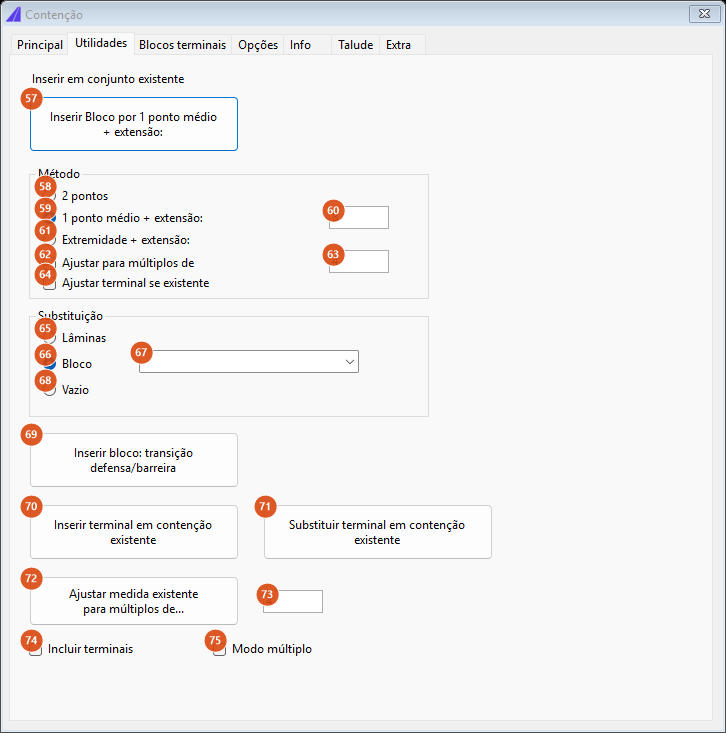
The Utilities tab: editing restraints that are already drawn.
This tab is a second set of tools, for editing existing restraints rather than creating new ones. None of its controls is available in this version. The controls are: Insert block by 1 mid point + length (57); the Method frame with 2 points (58), 1 mid point + length (59) and its box (60), End + length (61), Round to multiples of (62) and its box (63), and Adjust terminal if present (64); the Replacement frame with Beams (65), Block (66) and its list (67) and Empty (68); and the buttons Insert block: guardrail/barrier transition (69), Insert terminal in existing restraint (70), Replace terminal in existing restraint (71) and Round existing length to multiples of… (72) with box 73, Include terminals (74) and Multiple mode (75).
Tab 3: Terminal blocks
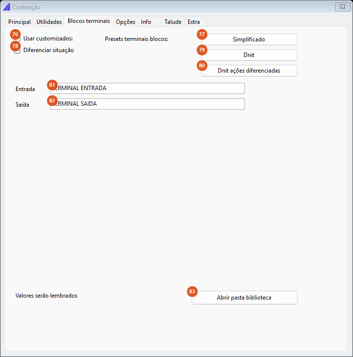
The Terminal blocks tab: the names used when option Blocks (17) is ticked.
| # | Control | What it does |
|---|---|---|
| 76 | Use custom: | No effect in this version: what turns this tab's names on is option Blocks (17) on the Main tab. |
| 77, 79, 80 | three preset buttons | Block-name presets. No effect in this version. |
| 78 | Differentiate status | Uses a different block per action. Keep, Remove and Replace are not available in this version, so all three fall back to the base name; Insert uses the base name by definition. |
| 81 | Entry | Name of the entry terminal block. Default TERMINAL ENTRADA. |
| 82 | Exit | Name of the exit terminal block. Default TERMINAL SAIDA. |
| 83 | Open library folder | No effect in this version. |
The Road restraint form stores nothing between sessions.
Tab 4: Options
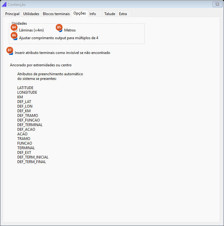
The Options tab: units, length rounding and the list of automatically filled attributes.
| # | Control | What it does |
|---|---|---|
| 84 | Beams (=4m) | The length boxes (4 and 7) start counting beams: each unit is worth 4 m. It never applies to the km boxes. |
| 85 | Metres | The length boxes are in metres. The default. |
| 86 | Round output length to multiples of 4 | Turns the whole length rounding on. Unticked, the body keeps the raw length of the parallel — and the minimum-length checks and the terminal clearance are skipped along with the rounding. |
| 87 | Insert terminal attribute as invisible if not found | No effect in this version. |
The list of attributes filled automatically when the terminal block has them: LATITUDE, LONGITUDE, KM, DEF_LAT, DEF_LON, DEF_KM, DEF_TRAMO, DEF_FUNCAO, DEF_TERMINAL, DEF_ACAO, ACAO, TRAMO, FUNCAO, TERMINAL, DEF_EXT, DEF_TERM_INICIAL, DEF_TERM_FINAL.
Tab 5: Info
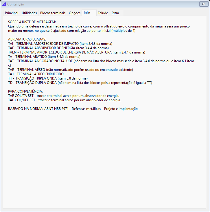
The Info tab: the text the form shows about the length rounding, and the glossary of terminal abbreviations with its norm reference.
This tab is text only; it has no controls.
Tab 6: Slope
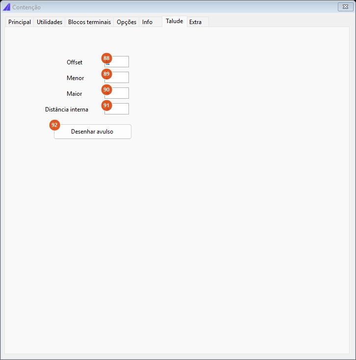
The Slope tab: the four numbers of the hatch drawn together with the guardrail.
| # | Control | What it does |
|---|---|---|
| 88 | Offset | Distance between the restraint body and the base line of the embankment hatch. Zero draws the hatch on the body itself. Default 5. |
| 89 | Smaller | Length of the short tick. Default 2. |
| 90 | Larger | Length of the long tick. Default 4. |
| 91 | Inner distance | Spacing between ticks along the base line. Default 3. |
| 92 | Draw standalone | Draw a slope hatch with no guardrail. No effect in this version. Use CAPCAD_ROAD_EMBANKMENT for that. |
The four values are only used when Add slope (54) is ticked on the Main tab. The hatch is described in detail on the embankment hatch page.
Tab 7: Extra
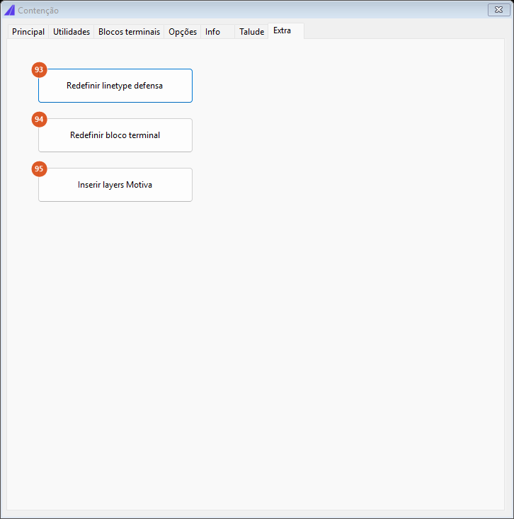
The Extra tab: three maintenance utilities.
None of the three has any effect in this version: Redefine guardrail linetype (93), Redefine terminal block (94) and Insert Motiva layers (95).
How the options combine
The figures below were produced by running the command's own positioning engine on a 340 m sample alignment (a straight, a curve and another straight), in the km to km method, from 0.040 to 0.260 — a 220 m stretch of alignment.
Offset and direction
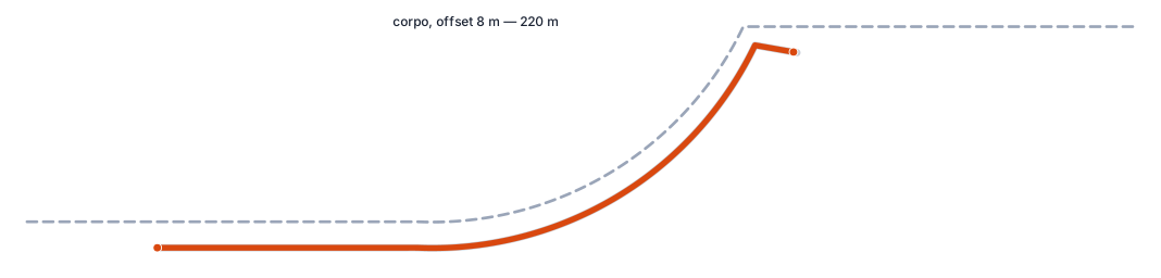
Offset 8 m, increasing direction: the body (orange) sits to the right of the alignment (dashed). Since part of the stretch is in a curve, the parallel came out at 221.08 m; rounded to multiples of 4 m, the delivered body is 220 m.
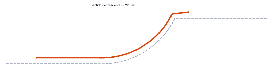
The same stretch in the decreasing direction: the body moves to the other side. On the inside of the curve the parallel shortens (219.24 m) instead of lengthening, and the rounding takes it to 220 m all the same.
Clearance for the terminals
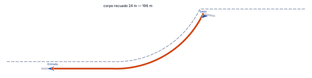
With No under "Terminal block overlapping the guardrail body", the body loses 12 m at each end: from 220 m to 196 m. The two terminal blocks (blue arrows) sit at the ends of the body, facing outwards — the entry one at the lower station, the exit one at the higher.
Multiples per object
The rounding uses the multiple of the chosen object. On the same stretch, the raw 221.08 m parallel becomes:
| Object | Multiple | Delivered length |
|---|---|---|
| Guardrail, Custom | 4 m | 220.00 m |
| Barrier | 1.50001 m | 220.50 m |
The batch insertion
CAPCAD_BATCH_RESTRAINT draws a whole road's worth of restraint from a pasted table. It is the natural destination of the stretch table the restraint analysis produces.
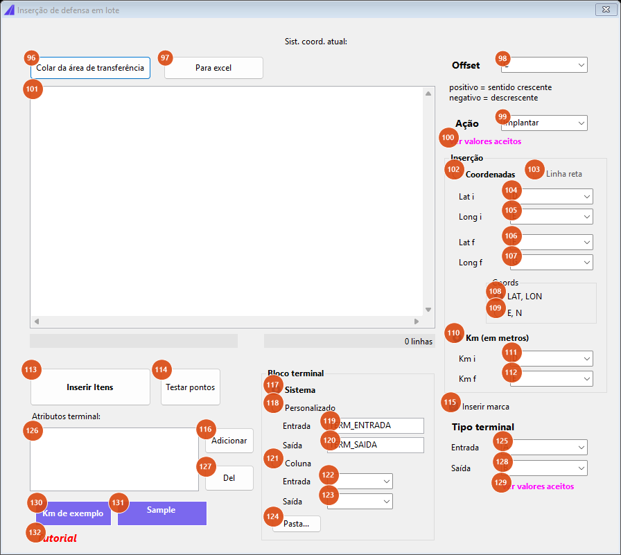
The batch form: the text area on the left takes the table, and the lists on the right say which column is what.
Each line of the text area is a stretch. The columns are separated by tabs — pasting straight from Excel already gives you that — and each list on the right names the column letter (A, B, C…) that datum comes from. A line with no tab at all is silently ignored.
The command uses the project's alignment (it asks for no selection) unless Straight line (103) is ticked. Each stretch is resolved by the same chain as the interactive form, and the body plus the two terminal blocks go to the action's layer (DEFENSA_IMP, DEFENSA_MAN, DEFENSA_REM or DEFENSA_SUB).
The controls
| # | Control | What it does |
|---|---|---|
| 96 | Paste form clipboard | Brings the clipboard text in, reports how many lines arrived and saves the text area. It appends the literal " linhas inseridas" to the end of the pasted text; the extra line has no tab and is therefore ignored. |
| 97 | To Excel | Sends the text area to Excel as a table. With no data, it warns. |
| 98 | Offset | The offset column. The sign gives the side: positive = increasing (right), negative = decreasing (left). The absolute value is the distance from the alignment. |
| 99 | Action | Either one of the four fixed words (Implantar, Manter, Remover, Substituir), or a column letter, in which case the action comes from each line. In the column, IMP, MAN, REM and SUB are also accepted. |
| 100 | See the accepted values | Shows the list of words accepted in the action column. |
| 101 | text area | The table. The counter below shows how many lines there are. On running, the content is saved in the exports folder and reloaded next time the form opens. |
| 102 | Coordinates | Each line carries the coordinates of the two ends, in columns 104 to 107. |
| 103 | Straight line | Coordinates mode only: the stretch is the straight segment between the two points, with no projection onto the alignment, no parallel and no length rounding. Of the offset, only the sign survives, giving the side. In this mode the project's alignment is optional. |
| 104 to 107 | Lat i / Long i / Lat f / Long f | The columns of the two ends. The labels change to Y and X when E, N (109) is chosen. |
| 108 | LAT, LON | The values are geographic and are converted into the project's coordinate system. |
| 109 | E, N | The values are already in the drawing's system. |
| 110 | Km (in metres) | Each line carries the start and end station, in columns 111 and 112. Despite the "Km" label, the values are read in metres. |
| 111, 112 | Km i, Km f | The columns of the two stations. |
| 113 | Insert items | Runs the batch. The form hides while it runs. At the end it shows, when there is one, the block report, the interruption message and the list of per-line errors. |
| 114 | Test points | Resolves the lines without drawing any restraint and marks the two ends of each stretch on the point-test layer, offering to frame the view on them. It is the way to check the table before drawing. |
| 115 | Insert mark | Inserts each stretch's two informative labels. |
| 116 | Add | Adds an attribute/column pair to list 126: first the column letter, then the attribute name. Each pair is written into both terminal blocks of that line. |
| 117 | System | Both terminal blocks are CapCad's default block. Only in this mode are the Terminal type lists (125 and 128) enabled. |
| 118 | Custom | Fixed names, typed in 119 and 120, the same for every line. |
| 119, 120 | Entry, Exit | The fixed names. Defaults TERM_ENTRADA and TERM_SAIDA. |
| 121 | Column | The block names come from table columns, given in 122 and 123. Before drawing, the command checks line by line whether each block exists and stops with a report if any is missing. |
| 122, 123 | Entry, Exit (column) | The columns of the block names. |
| 124 | Folder… | Opens the project's block library folder in Explorer. |
| 125, 128 | Entry, Exit (terminal type) | Columns carrying the terminal abbreviation, written into the block's attribute. Enabled only in System mode. |
| 126 | attribute list | Attribute → column pairs applied to each line's terminal blocks. |
| 127 | Del | Removes the selected pair from the list. |
| 129 | See the accepted values | Shows the glossary of terminal abbreviations. |
| 130 | Sample km | Fills the text area with seven sample lines in km mode, sets the matching columns and highlights the lists used in light blue. |
| 131 | Sample coordinates | The same for Coordinates mode, with geographic coordinates. |
| 132 | Tutorial | Opens the tutorial video in the browser. |
An empty column list means column A. The letters are upper case: a lower-case letter points at no column and the cell is simply not found.
What interrupts a batch
Three situations stop the whole run (the lines already drawn stay): in Coordinates mode, a coordinate column past the end of the line; in Km mode, both station columns past the end of the line; and, also in Km mode, only one of them past the end. Single-line errors — a point that does not project onto the alignment, two coincident points, an offset that fails — are listed in the final report and the batch carries on.
Remembered between sessions
The Road restraint form stores nothing: it always comes back to its initial state (km to km, Barrier, Increasing, Insert, offset detected from the point, terminals on in System mode, overlap Yes, reference km direction, rounding to multiples of 4 on).
The batch form stores: the terminal-type columns (125, 128), the four coordinate columns (104 to 107), the two station columns (111, 112), the Km / Coordinates choice (110, 102), the LAT, LON / E, N choice (108, 109), Straight line (103), the terminal block mode (117, 118, 121), the two fixed names (119, 120), the two block columns (122, 123) and the attribute list (126). The Offset (98) and Action (99) columns are written but not read back on opening. The text area is restored from the exports folder.
Notes
- With System (16) ticked and the Start and End boxes empty, no terminal is inserted. In that mode the typed type is used as a block name, and an empty name resolves to nothing; the command line lists "block not found". Type the terminal abbreviation in both boxes, or choose Blocks (17) and use the names from the Terminal blocks tab, or choose Actions (18) to fall back to the default block
DEF_TERMINAL_IMP. - The terminal names come out crossed. The block called entry gets the value of the End box and the exit one the value of the Start box. If the two abbreviations differ, check which end each one appears at.
- The station stamped on each terminal is the other end's.
DEF_KMandKMare read from the vertex opposite the one the block is inserted at. - The guardrail is drawn on the current layer. Only the batch insertion resolves the layer from the action. If you want the body on a restraint layer, make it current before clicking Insert, or use the batch.
- The slope hatch drawn with the guardrail also goes to the current layer, unlike
CAPCAD_ROAD_EMBANKMENT, which uses theTALUDElayer of the active catalogue. - The km methods refuse the value zero, so a stretch starting exactly at km 0+000 cannot be typed. Use 2 points in that case.
- The km + length method mixes two station readings. The start point is looked up by the raw measure along the alignment, but the end is computed from the normalised station. On an alignment starting at km 0 with no station equations the two coincide; on any other alignment, the end of the stretch may come out displaced. Check the result when the alignment's start km is not zero.
- The batch insertion exists only in AutoCAD in this version; on the other CADs it reports itself as not available.