| Commands | CAPCAD_PROFILE_MANAGER (vertical profile) · CAPCAD_PROFILE_DRAW (draw the project alignment's profile) · CAPCAD_SLOPE_QUERY (find slope) · CAPCAD_SURFACE_MANAGER (terrain surface) |
| Shortcut | PERF for CAPCAD_PROFILE_DRAW. The other three have no alias in acad.pgp |
| Ribbon | CapCad tab › Manage panel › Eixo split button › Perfil Vertical (CAPCAD_PROFILE_MANAGER) · Geo panel › Topo split button › Acha Inclinação (CAPCAD_SLOPE_QUERY) and the icon-only button with the Surface tooltip (CAPCAD_SURFACE_MANAGER). CAPCAD_PROFILE_DRAW has no button — see Notes |
| Categories | CAPCAD_SURFACE_MANAGER: CAD Utils: Layout tools. CAPCAD_PROFILE_MANAGER, CAPCAD_PROFILE_DRAW and CAPCAD_SLOPE_QUERY: NEW |
| Forms | VerticalProfileForm — CapCad Vertical Profile (modal; it hides while you click in the drawing and comes back) · SurfaceForm — Terrain Surface (modeless, three tabs). CAPCAD_PROFILE_DRAW and CAPCAD_SLOPE_QUERY have no form |
| Hosts | CAPCAD_PROFILE_MANAGER and CAPCAD_SURFACE_MANAGER: AutoCAD, BricsCAD, GstarCAD, ZWCAD and ARES Commander. CAPCAD_PROFILE_DRAW and CAPCAD_SLOPE_QUERY: AutoCAD only (in ARES running them shows a notice saying they are not available in this version) |
| Also opened by | The Análises perfil navigation button of the Road width form (CAPCAD_ROAD_WIDTH) opens CAPCAD_PROFILE_MANAGER; six buttons on the LandXML tab of the 3D assistant open CAPCAD_SURFACE_MANAGER |
The grade line is the datum missing from most signing drawings — and it is what decides gradient, sight distance and the warning signs that follow from them. Here the profile can be born from a field notebook, from a pasted list of latitude/longitude/elevation, or from online elevation data, and it comes out drawn with grid, levels, grades and VPIs.
- Three sources for the same grade line. Online elevation station by station, a list of points pasted from a spreadsheet, or a GPS file handed to the geographic-data converter.
- The profile becomes data, not just a drawing. The chosen polylines are stored on the alignment itself, with the station and elevation of the first vertex as the anchor.
- A complete drawing in one click. Curves, grade texts, VPI marks, a dimensioned grid and the stretch's planimetry — each with its own check box, and one button that erases everything that was drawn.
- Test before you commit. Test points against alignment plots the list as 3D points so you can see which ones fall within reach of the alignment before generating the grade line.
- Terrain surface without Civil 3D. A TIN triangulation built from points and breaklines in the drawing itself, or read from a LandXML, with section and contours in the same palette.
- Quick gradient query. Two clicks and the slope appears on the command line — in plan or, with the
Zkeyword, from the real elevations.
What it does
CAPCAD_PROFILE_MANAGER opens the CapCad Vertical Profile, the profile definition window. It does three independent things: generate the grade-line geometry from elevation data (Generate profile group), define which polylines of the drawing are an alignment's profile (Define profile group), and draw the defined profile with its annotations. It also erases the drawing, deletes the definition, frames alignment and profile, and leads to the profile analyses and to the auxiliary alignments.
CAPCAD_PROFILE_DRAW opens nothing: it takes the profile stored on the project alignment and draws its elements on the PROFILE_ALIGNMENT layer role — the name the active style resolved for that role. It is the PERF shortcut.
CAPCAD_SLOPE_QUERY asks for two points and writes the slope between them on the command line, to two decimals and always as an absolute value.
CAPCAD_SURFACE_MANAGER opens the Terrain Surface, a modeless palette holding a live surface in memory: you build it (from drawing points, from faces already drawn, or from a LandXML) and then cut sections and draw contours over it as many times as you like, without rebuilding.
Workflow
Generating the grade line from elevation data
- Run
CAPCAD_PROFILE_MANAGER. The project alignment must be defined. - Choose the source in the Generate profile group:
- Online data (Bing Maps) (3): the alignment is walked every Step (8) metres and the elevation of each station comes from the elevation service.
- Point list (6): the window widens and reveals the coordinates panel (36). Paste
latitude, longitude, elevation— separated by TAB or comma, one per line. - GPS file... (5): the window closes and CapCad opens the geographic-data converter.
- Set the Alignment distance limit (10): a point whose perpendicular projection on the alignment is beyond it is refused and goes into the failure report.
- Click Elevation: place points (2). The drawing must have a coordinate system defined — both paths reproject.
- The result is a polyline
station × (elevation × exaggeration)drawn on the active style's GIS points layer (list) or Bing points layer (online), and the view is framed on it. - If Draw grid (13) is ticked, the grid and the planimetry are drawn with it.
That polyline is the drawing of the grade line. To make it data, use Define profile right after.
Defining an alignment's profile
- Choose the mode in the Define profile group:
- Use CAD coordinates (17): the drawing coordinates already are station × elevation. No anchor is stored.
- Set initial values: (18): you give the Elevation (19) and the Start length (20) of the beginning of the profile, and CapCad stores the X and Y of the first vertex plus that station as the anchor.
- Click Define profile ... (14). In initial values mode the command asks you to confirm the two numbers before any selection.
- Select the alignment in the drawing.
- Select the profile polylines. They must all run left to right; one running the other way stops the operation with the warning at the bottom.
- In initial values mode, if the profile's length falls outside the alignment's length the command warns and asks whether to carry on (the excess is ignored).
- The chosen polylines are rewritten onto the profile's GPS data layer and the definition is stored on the alignment entity.
Drawing the defined profile
- Tick what you want: Curves (24), Grades (23), VPIs (25), Grid (26), Planimetry (27). At least one.
- Click Draw (21) and select the alignment that carries the definition.
- The grade texts come out at height 10, rotated in the direction of the gradient, with the value already divided by the Vertical exaggeration (29).
- Erase profile (31) erases everything on the six profile layers — nothing to select.
Querying the slope between two points
- Run
CAPCAD_SLOPE_QUERY. - At the first prompt, either click point 1 or type
Zto work from elevations. - Click point 2. The slope appears on the command line, as an absolute value to two decimals.
The normal path computes |100 × Δy / Δx| — the slope of the drawing. Over a drawn profile that is exactly the gradient; over the plan it means nothing. The Z path computes |100 × Δz / plan distance|, the real gradient between two elevations.
Building the terrain surface
- Run
CAPCAD_SURFACE_MANAGER. The palette opens on the Build TIN tab and the blue line at the top says there is no surface yet. - Build the surface one of three ways:
- Build from points ▶ (44): select POINTs and/or blocks; with Prompt for breaklines (43) ticked, the command asks for the breaklines next. At least 3 points are needed.
- From drawing… (45): select 3DFACEs or an already drawn mesh and CapCad reads the triangulation back.
- Load LandXML… (58): opens a surface
.xml. - The top line then shows how many points, how many triangles and the elevation range.
- With the surface live, use the other two tabs: Cut section ▶ (52) asks for the cutting line and the profile's base point; Draw contours ▶ (57) draws straight away.
- Save LandXML… (59) exports the live surface.
The surface is not stored in the drawing or in the project: it lives only while the palette is open.
The forms
The numbers are unique on this page: 1 to 38 in CapCad Vertical Profile and 39 to 60 in Terrain Surface. The screenshots are the Portuguese renders; the control positions are identical in every language.
CapCad Vertical Profile — CAPCAD_PROFILE_MANAGER
The window has two widths. It opens narrow and only widens when you tick Point list (6), revealing the coordinates panel on the right.
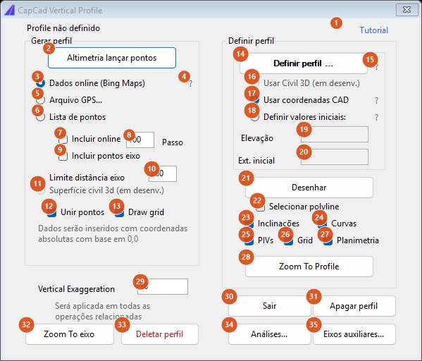
Factory defaults: online source, step 100, limit 200, CAD coordinates, exaggeration 10.
Generate profile group
| # | Control | What it does |
|---|---|---|
| 1 | Tutorial | Opens the vertical-profile video on YouTube |
| 2 | Elevation: place points | Runs the generation from the source ticked in 3/5/6 |
| 3 | Online data (Bing Maps) | Walks the alignment every Step and asks the elevation service for the elevation at each station. Ticked by default |
| 4 | ? | Reminds you that a profile from the online service is reference only and should not feed analytical criteria |
| 5 | GPS file... | Generates nothing here: it warns, closes the window and fires CAPCAD_GEO_CONVERT_DATA |
| 6 | Point list | Uses the text pasted in 36. It widens the window |
| 7 | Add online | Point list only: at the same stations as your points, it also asks for the online elevation and draws a second reference profile. When ticked, it warns that this is a good deal slower |
| 8 | Step | The interval, in metres, at which the alignment is walked in the online source. Default 100; an invalid or non-positive value goes back to 100 |
| 9 | Alignment points | Also draws, in plan, a POINT for every reprojected line of the list |
| 10 | Alignment distance limit | Maximum distance, in metres, between the point and the alignment for it to be accepted. Default 200; zero or negative refuses the run |
| 11 | Civil 3D surface (in devel.) | Not available in this version. |
| 12 | Join points | Not available in this version: the generated points always become a single polyline |
| 13 | Draw grid | Draws the grid and the planimetry over the profile just generated. Ticked by default |
Define profile group
| # | Control | What it does |
|---|---|---|
| 14 | Define profile ... | Stores the selected polylines as the profile of the chosen alignment entity |
| 15 | ? | Reminds you that you may retrace the profile over the original or draw your own field data, and that the definition need not be contiguous — several loose polylines count as one profile |
| 16 | Use Civil 3D (in devel.) | Not available in this version. To bring a profile in from Civil 3D, use the Civil 3D utilities |
| 17 | Use CAD coordinates | The drawing coordinates already are station × elevation. Default |
| 18 | Set initial values: | Anchors the profile: stores the X and Y of the first vertex plus the station typed in 20. Clicking inside 19 or 20 ticks this option on its own |
| 19 | Elevation | The real elevation at the start of the profile. It only serves the confirmation question — what is stored is the Y of the first vertex |
| 20 | Start length | The station of the alignment at which the profile begins. This is the one that goes into the anchor |
| 21 | Draw | Draws, over the stored definition, whatever is ticked in 22 to 27 |
| 22 | Select polyline | Not available in this version. |
| 23 | Grades | Gradient texts, one per straight stretch with a station Δ ≥ 10, at height 10 and rotated in the direction of the stretch |
| 24 | Curves | Draws the profile's own elements |
| 25 | VPIs | For each vertical curve, draws the two tangents extended to their meeting point — the VPI vertex |
| 26 | Grid | The profile's dimensioned grid |
| 27 | Planimetry | The stretch's planimetry strip, with the left and right curves on their own layers |
| 28 | Zoom To Profile | Asks for the alignment and frames the first element of the profile stored on it |
Bottom row
| # | Control | What it does |
|---|---|---|
| 29 | Vertical exaggeration | The vertical exaggeration, applied in every operation of the window: it multiplies the elevation when the profile is generated and divides the gradient when it is labelled. Default 10 |
| 30 | Exit | Closes the window |
| 31 | Erase profile | Erases every entity on the active style's six profile layers. It does not ask and does not want a selection |
| 32 | Zoom To alignment | Asks for a curve and frames it |
| 33 | Delete profile | Asks, requests the alignment and removes the definition stored on it. It erases no drawing |
| 34 | Analyses... | Closes the window and opens the profile analyses |
| 35 | Auxiliary alignments... | Closes the window and opens the auxiliary alignments (CAPCAD_ALIGNMENT_AUXILIARY) |
Coordinates panel (only with Point list)
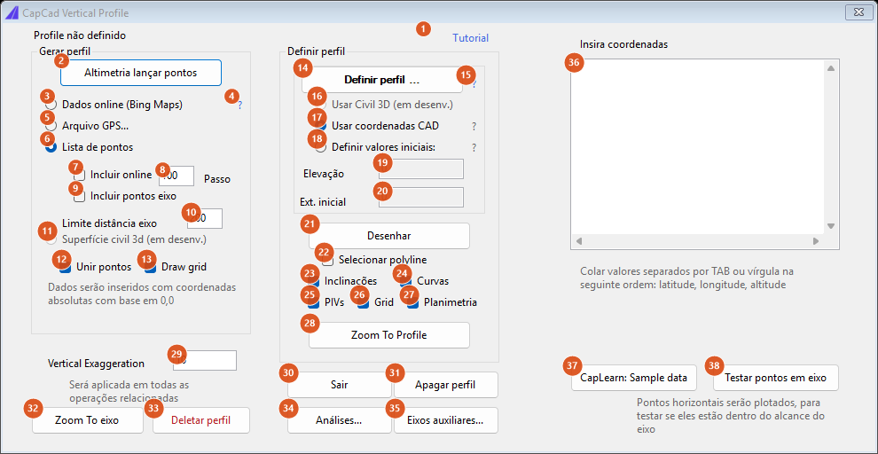
| # | Control | What it does |
|---|---|---|
| 36 | (coordinates list) | One line per point: latitude, longitude, elevation, separated by TAB or comma. Lines with fewer than three fields are silently ignored. The line counter sits just below |
| 37 | CapLearn: Sample data | Fills the list with the 1,201 points of the sample project, after reminding you that the Sample Project alignment must be loaded |
| 38 | Test points against alignment | Plots the lines as 3D POINTs on the GIS points layer and frames the set, generating no profile at all. Above 100 lines, it asks whether you want only the first 100 |
Below the list, three informational labels: the project's coordinate system, the number of lines typed, and Mostrando última tentativa when the contents were reloaded from the profile_gpspoints.txt file.
Terrain Surface — CAPCAD_SURFACE_MANAGER
The blue line above the tabs is the state of the live surface: Surface: N points · N triangles · Z min – max, or the notice that there is none yet. The three bottom buttons (58 to 60) apply on any tab.
Tab 1: Build TIN
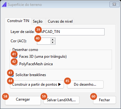
| # | Control | What it does |
|---|---|---|
| 39 | Output layer: | The layer the triangulation is drawn on. Default CAPCAD_TIN; left blank it goes back to the default. It is the name as typed — see Notes |
| 40 | Colour (ACI): | The colour of the created layer. Default 8 |
| 41 | 3D faces (one per triangle) | One 3DFACE entity per triangle. Default |
| 42 | Single PolyFaceMesh | One single mesh, with shared vertices. Above 32,767 vertices the command warns and falls back to 3D faces on its own |
| 43 | Prompt for breaklines | After the points, also asks for the breaklines (polylines and lines). Ticked by default; Enter skips |
| 44 | Build from points ▶ | Asks for POINTs and blocks, triangulates and draws |
| 45 | From drawing… | Reads an existing triangulation (3DFACEs or mesh) into memory, drawing nothing |
Tab 2: Section
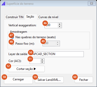
| # | Control | What it does |
|---|---|---|
| 46 | Vertical exaggeration | Multiplies the elevation axis of the drawn section. Default 1, minimum 0.01, maximum 100 |
| 47 | At terrain breaks (exact) | Samples the line exactly at every crossing with a TIN edge — inside a triangle the terrain is flat, so this gives the exact profile. Default |
| 48 | Fixed step (m): | Samples at a fixed plan distance instead of at the crossings |
| 49 | (step) | The step, in metres. Only enabled with 48 ticked. Default 1 |
| 50 | Output layer: | The layer of the section polyline. Default CAPCAD_SECTION |
| 51 | Colour (ACI): | Default 3 |
| 52 | Cut section ▶ | Asks for the cutting line (or the alignment) and then for the base point where the profile will be drawn; the section grows from there |
Tab 3: Contours
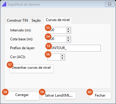
| # | Control | What it does |
|---|---|---|
| 53 | Interval (m): | The contour spacing. Default 1 |
| 54 | Base elevation (m): | The elevation the levels are counted from. Default 0 |
| 55 | Layer prefix: | Every level goes to its own layer, prefix + elevation: CONTOUR_15, CONTOUR_16… Default CONTOUR_ |
| 56 | Colour (ACI): | The colour of every contour layer. Default 3 |
| 57 | Draw contours ▶ | Draws one closed or open polyline per trace, each with the elevation of its level |
Bottom row
| # | Control | What it does |
|---|---|---|
| 58 | Load LandXML… | Replaces the live surface with the surface from an .xml file |
| 59 | Save LandXML… | Writes the live surface to LandXML |
| 60 | Close | Closes the palette. The live surface is lost |
How the options combine
The three places a "profile" can live
This is the part that confuses most, and it is worth reading slowly. In this version there are three profile stores, and they do not talk to each other:
| Where | Who writes it | Who reads it |
|---|---|---|
| On the drawing's alignment entity | Define profile (14) of this window | Draw (21), Zoom To Profile (28) and Delete profile (33) of this same window |
| On the project alignment (the alignment file) | Profiles › Load of the Civil 3D utilities | CAPCAD_PROFILE_DRAW, the Draw / Zoom / Identify / Grades buttons of the Civil 3D utilities, and the Profile not set label at the top of this window |
| Nowhere — you select the polyline at the time | — | The profile analyses (CAPCAD_ANALYTICS_VERTICAL_OVERTAKING) |
The practical consequence: defining the profile here does not make CAPCAD_PROFILE_DRAW draw it, and it does not feed the analyses. See Notes.
What the vertical exaggeration does in each operation
The profile is drawn at x = station, y = elevation × exaggeration — 10 by default, because a 3% gradient over a 2 km stretch would be invisible at the plan scale.
| Operation | How the exaggeration comes in |
|---|---|
| Generating the profile (2) | Multiplies each elevation before it becomes a vertex |
| Grade texts (23) | The drawn gradient is divided by the exaggeration, so the text shows the real gradient |
| Grid and planimetry (26/27) | The elevation scale of the grid comes from the stored anchor |
CAPCAD_SLOPE_QUERY without Z |
It does not. The command returns the drawing's gradient: over a profile at 10×, ten times the real gradient |
CAPCAD_SLOPE_QUERY with Z |
It does not, and does not need to: it works with the real Z of the two points |
Where each thing is drawn
| Operation | Layer |
|---|---|
| Profile generated from the point list | Role PROFILE_GIS_PONTOS |
| Profile generated online, and the reference one of 7 | Role PROFILE_GIS_GMAPS |
| Test points against alignment (38) | Role PROFILE_GIS_PONTOS |
| Define profile (14) and Curves (24) | Literal name PROFILE_GPS_DATA, colour 53 |
| Grades (23) | Literal name PROFILE_ANNO, colour 3 |
| VPIs (25) | Literal name PROFILE_ANNO_PIV, colour 12 |
| Grid and Planimetry (26/27) | Roles PROFILE_CURVE_TANGENT, PROFILE_CURVE_LEFT, PROFILE_CURVE_RIGHT, PROFILE_GRID and PROFILE_ANNO |
CAPCAD_PROFILE_DRAW |
Role PROFILE_ALIGNMENT |
| TIN, section and contours | The names typed in fields 39, 50 and 55 |
Where the table says role, the real layer name is whatever the active style resolved for it. Where it says literal name, the layer is created with exactly that name — see Notes.
How the section is sampled
In exact mode (47), the cutting line is intersected with every TIN edge and sampled at each crossing, plus its own vertices. Because the terrain is flat inside a triangle, that gives the exactly right profile, with the fewest possible vertices. The fixed step mode (48) is simpler and more predictable, but it cuts corners: a terrain break between two samples is lost.
A cutting point that falls outside the surface stops nothing — it gets elevation zero, and the section dives there. It is worth checking that the cutting line fits entirely inside the TIN.
Remembered between sessions
The CapCad Vertical Profile saves all its controls in the preferences — source, step, limit, exaggeration, definition mode and the drawing boxes come back as you left them. The point list is left out of that: it has its own file, profile_gpspoints.txt, written into the exports folder at every run of Elevation: place points and reloaded on the next opening, with the Mostrando última tentativa notice.
The Terrain Surface saves nothing: layers, colours, interval and exaggeration go back to the factory defaults at every opening, and the live surface dies with the palette.
Notes
CAPCAD_PROFILE_DRAWhas no ribbon button in any country profile. The command is reachable through thePERFalias or by typing the full name.- The profile defined here does not feed
CAPCAD_PROFILE_DRAWor the analyses. Define profile stores the definition on the alignment entity;CAPCAD_PROFILE_DRAWand the Civil 3D utilities read the profile from the project alignment; and the profile analyses want you to select the polyline at the time. All three paths use the same word for different stores. Use Draw (21) in this window for the profile you defined here, and keepCAPCAD_PROFILE_DRAWfor the profile brought in from Civil 3D. - The label at the top of the window looks at the other store. On opening, Profile set / Profile not set is read from the project alignment. After you click Define profile or Draw, it starts reflecting the selected entity. An alignment with a stored definition can therefore open the window saying Profile not set.
- Three of the profile drawing's layers have fixed names. Define profile, Curves, Grades and VPIs always create
PROFILE_GPS_DATA,PROFILE_ANNOandPROFILE_ANNO_PIV, independent of the style, while Erase profile (31) erases the layers the style resolved for those roles. With a style that renames or prefixes layers, erase the three fixed-name layers yourself; with the default style the names coincide. CAPCAD_SLOPE_QUERYmeasures the drawing, not the terrain. Without theZkeyword it computesΔy/Δxin drawing units: it is the right tool over the profile, and you have to remember to divide by the exaggeration to get the real gradient. Over the plan, the number has no meaning.- Two cancellations behave differently in
CAPCAD_SLOPE_QUERY. Esc at the first point ends the command; Esc at the second makes the command reportinclinação = 0.00 %. Two points on the same vertical (Δx = 0) also return0.00 %. - Not available in this version: Join points (12) — the generated points always become a single polyline —, Select polyline (22), Civil 3D surface (11) and Use Civil 3D (16).
- A few strings stay Portuguese whatever the interface language: the Mostrando última tentativa notice, the slope report (
inclinação = 0.00 %) and the surface palette's status line and messages. - The online elevation is an external service. A network or reprojection failure aborts the whole run — not even the points already processed are drawn. Progress is shown in blocks of 100 points and the bar can be cancelled.
- The refused-points report opens in its own window. The points that fell beyond the Alignment distance limit are listed as
line ⇥ contents, so you can find the wrong row in the source spreadsheet. - The terrain surface is volatile and its layers are typed by hand. Closing the palette discards the triangulation; fields 39, 50 and 55 create layers by the name you wrote, independent of the style: they get the colour typed beside them and no other property.
- A section only makes sense inside the TIN. A sampling point outside the surface comes in with elevation 0 instead of being dropped, which produces a step down to zero in the drawn profile.
- Contours create one layer per level. A small interval over broken terrain can create hundreds of
CONTOUR_*layers. Check the Interval (53) before clicking.
See also
- Navigating the alignment — framing alignment and profile side by side and interlocating points between them.
- Draw and edit the alignment — the auxiliary alignments the profile is stored beside.
- Alignment Manager — the project alignment the profile is paired with.
- Station Navigator — reading elevation and gradient at a picked station.